This thread has been locked.

If you have a related question, please click the "Ask a related question" button in the top right corner. The newly created question will be automatically linked to this question.

UCC27211: Timing Diagrams confirm

Part Number: UCC27211

Tool/software:

Hi Team,

 About the UCC27211 Timing Diagrams, it is known that the UCC27211 do not have a interlock function, so if the HI LI input high, the HO & LO will output together.

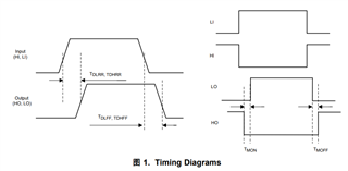
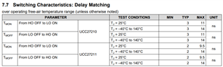
but the below diagrams,  it is clear to understand the TDLRR parameter is the time between input and output.

1)and the Delay Matching is a little confuse here,  if the HI(low)+LI(high) input together, why HO will drop first and LO will need type 2ns to rise up, why can not the LO rise up first and HO drop down after 2ns?

2)if the UCC27211 do not have a interlock function ,the HO & LO can output together, why we still need the delay matching here to prevent short circuit here?

tks for the checking here. 

  • Hey Allen,

    Thank you for reaching out with your questions regarding the UCC27211.

    1. If HI and LI are switched simultaneously, the variance in the output time of HO and LO will be 2ns typically. This means that the sequence of LO and HO transitioning can either be LO then HO or HO then LO, but they variance will be approximately 2ns. So, if you switch LI and HI simultaneously, then there could potentially be shoot through as this device does not have interlock.

    2. The delay matching spec is not there to prevent shoot through, it is for variances in prop delays in the LO and HO channels when switching simultaneously and does not prevent shoot through on the output. It is not advised to switch HI and LI simultaneously as deadtime is needed to prevent shoot through.

    Let me know if there are any further questions.

    Thank you,

    William Moore

  • Hi William,

     tks for the comments here, but it is still not so clear to understand this explanation.  such as the TDLRR has 10~40ns Propagation Delays time.

     and if we switch the HI/LI simultaneously, maybe the HO need 10ns and LO need 40ns to output ,then we will have 30ns as Delay Matching time here? but the TMON only have 2~14ns here, so can you help to explain more?

    The delay matching spec is not there to prevent shoot through, it is for variances in prop delays in the LO and HO channels when switching simultaneously
  • Hello Allen,

    Apologies but our expert is out of office today, and he will get back to you next week.

    Thanks,

    Walter

  • Hello Allen,

    William is out of the office for a couple of days, but I can work to address some of your questions.

    There is a variance in the propagation delays of input to output that can vary more that the channel to channel delay matching. I am not reviewing the datasheet but I will take your 10-40ns as the input to output delay time min to max variance. 

    Both driver channels can have a total delay variance based on temperature that will affect the total delay. However the total delays of both channels vary together which results in a channel to channel delay matching that is lower than the total delay variation of input to output. 

    What William was providing the concern on cross conduction is that if both inputs switch at the same time, with the delay matching variance, there can be some small time of cross conduction, there is no guaranteed dead time. And there is no logic to prevent the LO and HO from both being high if both LI and HI are high at the same time.

    Can you clarify the concern of the driver timing in this application? The driver outputs will follow the controller generated driver inputs, the controller needs to provide the desired timing and dead time.

    Regards,

  • Hi Richard,

     tks for the comments here.

     So it is clear that:

     propagation delays   --->input to output

     delay matching------->channel to channel

     we can accept the LO and HO high simultaneously, due to it do not have a interlock function here. 


    but more question about the delay matching , for UCC27211, it is a two Independent driver , why we have to consider the delay between two channel?  each channel will have 10~40ns propagation delays time, so for two channel , it must have different output time.

    Take an extreme example, if two channel work as the same temp and they both take 20ns from input to output, Theoretically, there should be the same output time, and them which channel need add the delay matching time like 2ns.

     then it may change to  :  (delay matching as 2ns)

     channel 1 : 0-> input-output 20ns +2ns

     channel 2 : 0-> input-output 20ns +2ns

    or 

     channel 1 : 0-> input-output 22ns +4ns

     channel 2 : 0-> input-output 24ns +2ns

    at the end ,the HO LO will both connect simultaneously, so why still need the delay matching here?

  • Hey Allen,

    The delay matching between each channel is specified to verify and ensure that the inputs that are provided are consistent and there is not a chance for overlap and shoot through when designing the control system. When optimizing the deadtime, it is important to consider the rise and fall times as well as the potential difference between HO and LO to ensure that enough deadtime is in place to avoid shoot through. So, the controller that provides HI and LI signals should be designed for sufficient deadtime between HI and LI so that HO and LO do not overlap and cause shoot through.

    Here is a short clip about Delay Matching:

    Know Your Gate Driver: Delay Matching

    In your example, if both channels are switching simultaneously, and then the delay between the two signals on the output is typically 2ns. You would have a case like this:

    HO Channel -> input-output 19ns

    LO Channel -> Input-output 21ns

    LO prop - HO prop = 2ns (typical delay matching)

    So, when switching the simultaneously, the typical difference between HO and LO channels can be 2ns.

    Thank you,

    William Moore

  • hi  William,

     tks for the comments here, it is clear now, but the UCC27211 do not have a interlock function, it can short circuit here, so why we still need to care how to  avoid shoot?

  • Hey Allen,

    Yes the UCC27211 does not have interlock, so it can allow shoot through if both outputs are on at the same time. The delay matching spec is not provided to avoid shoot through, it is included in the datasheet to ensure the consistency of both channels. If you transition both channels at the same time, it is likely that you will encounter shoot through. This can be due to variances in the PWM input signals and the rise and fall time of the MOSFETs. Shoot through avoidance should be handled by the deadtime and programming of the controller and not the gate driver.

    Thank you,

    William Moore