- Ask a related questionWhat is a related question?A related question is a question created from another question. When the related question is created, it will be automatically linked to the original question.
This thread has been locked.
If you have a related question, please click the "Ask a related question" button in the top right corner. The newly created question will be automatically linked to this question.
Tool/software:
Hi Team,
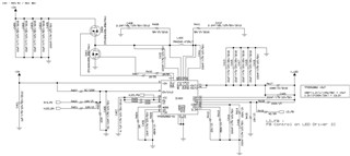
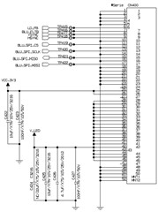
I'd like to request the layout design review of TPS552882-Q1. Please check the attachments below and let me know if you need the additional information.


Regards,
Hi Jeffery,
Thank you for reaching out. I will look into this later.
Regards,
Mulin
Hi Jeffery,
Sorry for delayed reply. I was out of office because of public holiday.
About schematic:
1. What is input voltage and output current?
2.What is saturation current of inductor?
3.Recommend to change R408 and R411 to 2ohm.
4.Current compensation parameters are not suitable. Please provide working spec and output cap part number for calculation.
About layout, the gerber file is empty with AD. Can you help provide PDF version?
Regards,
Mulin
Hi Mulin,
Please check my answers and attached layout pdf file below.
1. What is input voltage and output current? Vin=12V(typ.) and Iout=5A(typ), 12A(max.)
2.What is saturation current of inductor? ISAT=17A(PM4342.NLT of PULSE supplier)
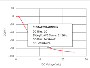
4.Please provide working spec and output cap part number for calculation. Their spec of gain and phase margin are not fixed yet, but they want the phase margin of over 60-degree. Output capacitor's part numbers are CL31A226KAHNNNE(22uF, C413/C415/C417/C418) and MCASU105SB7104KFNA01(100nF, C419).
Regards,
Hi Jeffery,
Considering typical Vin range:9-16V, then maximum input current will be 13.2*12/0.95/9=18.5A. This is out of TPS552882-Q1 SPEC. TPS51772-q1 is more suitable here. Can you help check with customer?
Regards,
Mulin
Hi Mulin,
Please consider the input voltage range of 5V to 36V. I couldn't find TPS51772-Q1 on TI.com. Please check the correct part number.
Regards,
Hi Jeffrey,
I am sorry for confusing you. It is LM51772-Q1. I will involve related expert to this thread. Feel free if you have any problem.
Regards,
Mulin
Hi Jeffrey,
just let me know if you have any questions regarding the LM51772.
Best regards,
Stefan
Hi Stefan,
LM51772-Q1 is not released yet, so please let me know the expected release plan of AEC-Q100 qualified device.
Regards,
Hi Jeffrey,
LM51772-Q1 will RTM in 2Q25, the LM51772 sample(commercial) is available now but the Automotive samples are only available late 4Q24.
Best regards,
Yezi
Hi Mulin,
There is the update for this case. LED zone is defined and max. input current is changed. So please continue the layout design review.
- LED zone : 798, Vout =15V / 5mA (total current of LED zone=4A), max. input current=15*4/0.95/9=7A
Regards,
Hi Jeffrey,
About the schematic, the 4*22uF cap only have 17.6uF effective capacitance. This is not enough for a 60W application. Can customer change better ceramic capacitors or add a large e-cap?

About the layout, please pay attention to cross connection , VCC cap connection and AGND/PGND connection.TPS552882Q layout reiview 09242024.pptx
Regards,
Mulin
Hi Mulin,
Thanks for your support. Let me check it with customer and update their feedback.
Regards,
Hi Mulin,
I got the updated layout file from customer. Please review it again.
Regards,
Hi Jeffrey,
Our engineer is currently out of office, please expect a reply by Wednesday. Thank you for your patience.
Best regards
Yezi
Hi Jeffrey,
I cannot open the file. Can you provide PDF version?
Regards,
Mulin
Hi Mulin,
Please check the layout file of pdf version. Please let me know your email if you can't recognize it.
Regards,
Hi Jeffrey,
My email is mulin-yuan@ti.com. It will be better if you can send me the origin AD file.
Regards,
Mulin