This thread has been locked.
If you have a related question, please click the "Ask a related question" button in the top right corner. The newly created question will be automatically linked to this question.
Tool/software:
Hello all
I am using BQ77915 IC for cell balancing in a three cell battery.
I selected 3 cells whose voltages were 3.66V, 3.65V and 3.59V for charging.
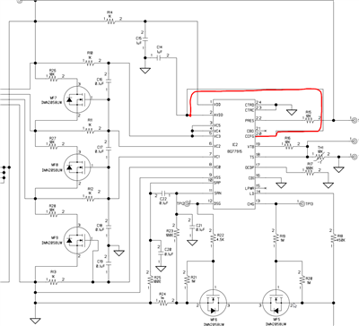
I am using external MOSFETS as per the recommended circuit in datasheet.
I turned ON the charging circuit and the cells charged gradually. The voltages of all the cells increased gradually.
Some of the voltages captured at different time instances are as follows:
at Tx - 3.8V, 3.78V, 3.7V
at Ty - 3.9V, 3.89V, 3.77V
at Tz - 4.17V, 4.15V and 3.98V
The voltages were captured at more instances but I am not mentioning those here.
At Tz, the charging MOSFET was turned off.
Through out this charging time, I observed the signal on the oscillosope, at the drain of the external MOSFETS.
There should have been cell balancing pulses at any of the drain terminals. But there were none ; which means there was no charge balancing.
What could be wrong....
Hello Vijay,
Have you seen our video for cell balancing using this device?
https://www.ti.com/videolist/foldersGallery?bkg=gray&gpn=1895177
I would also recommend to check with the oscilloscope directly on the pins to see if the device is attempting to balance.
Best Regards,
Luis Hernandez Salomon
I checked the signals on the pins of IC77915. There was no difference. But how is it different to probe the signals on the IC pins or on the components connected to the pins. Kindly advise..
Attached is the circuit diagram.BMS - circuit diagram for Texas Ins forum.pdf
Hello Vijay,
Measuring at the pins would indicate if the part is attempting to balance. As it will show the balancing on the waveform, similar to what is shown in the video I shared.
From your schematic, I see that one of the cells may not be properly configured. I see your CCFG pin is connected to AVDD, which would typically mean that the device is configured for 4s. But I see 3s in your system.
Additionally, what is your charging current?
Best Regards,
Luis Hernandez Salomon
CCFG is connected to ground or Vss. The triangle indicates Vss. The charging current is 600mA
Regards
Vijay Kumar M
Hello Vijay,
You may have sent me the wrong schematic, the schematic you shared shows CCFG connected to AVDD:
Now, 600-mA is too small to detect a "charging" current, which is required for cell balancing.
For a charging current to be detected, there needs to be a 1.875-mV voltage drop across the sense resistor. This would correspond to 1.875-A of charging current when using a 1-mOhm sense resistor.
If you increase charging to higher than this value, does balancing work?
Best Regards,
Luis Hernandez Salomon
Hello Luis,
Thanks for your timely reply. The circuit diagram I had sent u was indeed a different one. In the actual circuit CCFG is connected to VSS.
We cannot increase the charging current and hence I changed the sense resistor to 10mohm ; and the balancing pulses are seen.
But there is another problem; although balancing happens, one of the cells reaches the Over Voltage (4.1V) threshold, resulting in fall of CHG line.
When CHG line falls from 10V to 0V, all the cell voltages fall by 0.1V, and the cell mentioned above falls to a value below Over voltage - V hyst . Consequently the CHG line turns ON and reaches 10V, and the cell voltages are added with 0.1V, resulting in overvoltage. The CHG line turns off and the cycle continues.
What could be wrong.
Hello Vijay,
There are a few reasons this could happen:
Best Regards,
Luis Hernandez Salomon