This thread has been locked.
If you have a related question, please click the "Ask a related question" button in the top right corner. The newly created question will be automatically linked to this question.
Tool/software:
Hi,
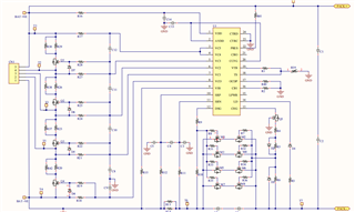
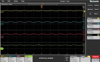
I have designed BMS with Internal Cell Balancing using BQ7791506. But Cell Balancing not working .Please see the test results below:
4 Cells are in Series. 5AH Battery
Before Charger Connected - Cell Voltages
Cell - 1 -- 3.34V
Cell - 2 -- 3.34V
Cell - 3 -- 3.34V
Cell - 4 -- 3.30V
After Charger Connected - Cell Voltages (Time: 10.08AM IST)
Cell - 1 -- 3.47V
Cell - 2 -- 3.47V
Cell - 3 -- 3.46V
Cell - 4 -- 3.39V
Cell Voltages (Time: 10.13AM IST)
Cell - 1 -- 3.52V
Cell - 2 -- 3.53V
Cell - 3 -- 3.51V
Cell - 4 -- 3.38V
Cell Voltages (Time: 10.27AM IST)
Cell - 1 -- 3.66V
Cell - 2 -- 3.62V
Cell - 3 -- 3.51V
Cell - 4 -- 3.34V
Here 4th Cell is at down side and that cell is started discharging but other cells are charging more than 3.5V. But as per datasheet for BQ7791506 cell balancing start at 3.5V. No cell balancing observed Please explain the what's the problem and why Cell 4 is only discharging more. I have used Rin resistor 33E and Cin 1uF
Hello,
BQ77915 utilizes passive cell balancing. This means that current is redirected away from a cell, making it charge slower. You are correct BQ7791506 has a VSTART of 3.5V. However, cell balancing is based on a threshold. Cell Voltages need to be below VCBTL and above VCBTH for cell balancing to occur. In addition, cell balancing will only occur in the cells above VCBTH. In your case only cells 1 and 2 are balancing.
You can refer to the "How the cell balancing feature works for the BQ77915" video for more information.
If you wish to increase balancing current above 50mA you can refer to the data sheet for using external MOSFETs.
Best regards,
Thomas Rainey
Hi Thomas,
Thanks for quick response.
Still I need clarification on cell 1 and cell 2 balancing in my case. As per BQ7791506 datasheet cell Balance should start above 3.6V. But in my case even at 3.66V , the cell voltage is rising more (I observed 3.73V also sometimes). Actually that cell voltage should decrease. Why cell 4 voltage is going down 3.39 to 3.34V (down cell which is connected to VC0 pin). Please clarify this.
Thanks
Jaya Prasad
Hello Jaya,
Is this an isolated problem or is it happening with different battery packs?
Can you send your schematic?
Best regards,
Thomas Rainey
Hi Thomas,
Thanks for coming back. Please see the attached schematic and review and suggest any modifications.
Best Regards,
Jaya PrasadSGS1_Project-5 (1).PDF
Hi Jaya,
In your original post you stated you used Rin as 33Ω and Cin as 1μF. However, since you are using external MOSFETs for cell balancing the value should be 1kΩ for Rin and .1μF for Cin.
Can you clarify the values of R17, R27, R24, R21, and R18? As well as, C12, C11, C10, C8, C9?
Best regards,
Thomas Rainey
Hi Thomas,
In your original post you stated you used Rin as 33Ω and Cin as 1μF. : Yes Thomas, You are correct. Initially I tested with External MOSFETs for cell balancing and observed that same results as observed with Internal Balance circuit. And then I suspect that may be a problem in External MOSFETs and changed to Internal Balancing circuit. But no change in test results and observed same in both internal balancing and external balancing circuits.
For Internal Balancing Circuit I have used Rin as 33Ω and Cin as 1μF.
Can you clarify the values of R17, R27, R24, R21, and R18? As well as, C12, C11, C10, C8, C9?
R17, R27, R24, R21, and R18 - 1K
C12, C11, C10, C8, C9 - 100nF
the above values used for external cell balancing.
MOSFET (Vgth: 1V)SSN0204.pdf
So I tried both circuits and used Rin and Cin values accordingly. But no change in test results.
Thanks
Best Regards,
Jaya Prasad.
Hi Jaya,
Can you send a waveform measuring the voltage at VC0, VC1, VC2, VC3, and VC4 pins when the device should be cell balancing? This is to double check the device is cell balancing.
Best regards,
Thomas Rainey
Hi Thomas,
Please see the attached waveforms at VC1,2,3,4 pins before charging, During charging and Full charge stages and also attached test results observed..
Please review and give your valuable suggestions or modifications if any required.
Best Regards,
Jaya Prasad
Hello Jaya,
It looks like the cells are only balancing when the cells are on a full charge.
Best regards,
Thomas Rainey
Hi Thomas,
No. It's with one battery pack consist of 4 Cells in Series (3.2V Cells, Max Cell Voltage: 4.1V)7635.bms.pdf
Please see the attached schematic with component values,
I tested with internal cell balancing only.
Please
Best Regards,
Jaya Prasad
Hi Jaya,
I don't see anything wrong with the schematic. Can you try switching cell 4 out with a different cell and see if the issue persists?
Best regards,
Thomas Rainey
Hi Thomas,
My problem was resolved by replacing the cell.
One more question: Can I use this BMS design upto 200AH Battery ( By optimise the MOSFET ratings) or Not. If not, Please suggest which one is suitable for higher AH Battery BMS.
Thanks,
Best Regards,
Jaya Prasad
Hi Jaya,
In addition to the MOSFETs, the sense resistance would need to be changed to match the difference in the OCC/OCD/SCD values of the new battery, and also to match the increased power dissipation.
Regards,
Max Verboncoeur
Hi Max,
Thanks for your suggestions and clarification on this .
Best Regards,
Jaya Prasad