This thread has been locked.

If you have a related question, please click the "Ask a related question" button in the top right corner. The newly created question will be automatically linked to this question.

UCC256404: Steady state frequency much higher then calculated

Part Number: UCC256404

Tool/software:

Hi,

I designed an LLC using the UCC256404 controller, for the design I used the excel sheet and the simplis model to calculated the values and simulated the model which all went fine. Now that I'm measuring I'm seeing some discrepancy's with regarding the switching frequency.

Spec's

48Vin 
24Vout
6.5A max load
Desired resonance frequency 125kHz
Transformer 10:12
Lp = 50.2uH (measured)
Llk = 2.2uH (measured while shorting secondary)
6.8uH external resonance inductor
177nF resonance capacitor
Burst disabled

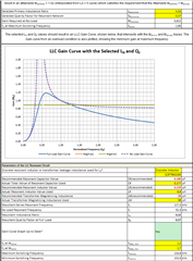
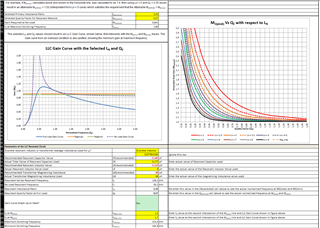
So I started with the excel sheet during the design and came with the values given above (transformer was chosen as staring point not ideal ratio).
The excel sheet showed a frequency range of 160kHz to 220kHz for full load range (fixed input voltage) and for a load of 1A the expected frequency would be 1.3 timed Fn so 1.3*125kHz=162.5k

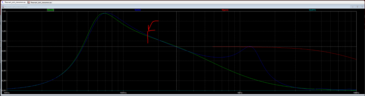
But measurement showed roughly 280kHz so much higher then expected, so I started to what is wrong and my conclusion was that the gain of the resonant tank was higher then expected so did some measurement on the resonant tank.


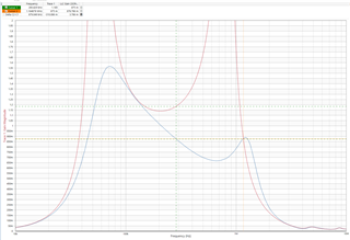
Red is LLC gain no load
Blue is LLC gain with 22ohm load (roughly 1A)

Which showed my conclusion that the needed gain of 0.88 was reached at around 280kHz this graph did not match the excelsheet at all so I must have filled in some wrong values.

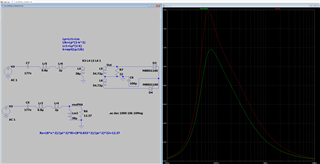
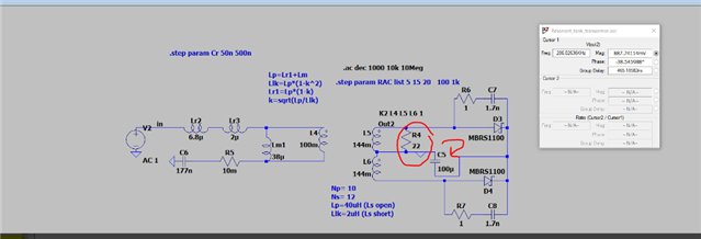
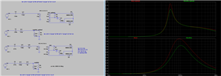
To verify I made simulation model based on the measurement and show roughly the same values

Spice simulation with 4ohm 22ohm and 1kOhm of resistance.

So the big question why is the excelsheet different from measurement ? I also tried the integrated inductor but also different values.

4721.UCC25640x Design Calculator Rev4.0.xlsx

  • We will review it and get back to you asap

  • Hello,

    I am reviewing your inquiry and will get back to you shortly.

    Regards,

  • Hello,

    The gain is quite a bit off.  Could you double check your Cr, Lm and Lr?

    Please note Lr is really Lr + Llk.

    Please note the tool calculates Cr.  If your design is using a capacitor divider off the input each capacitor should be Cr/2.

    If you entered the incorrect Cr in the tool this could cause the plot to be off as well.

    Regards,

  • Hi Mike,

    Thank you for the reply yesterday I did some more measurements and spice simulations,  we don't have capacitor divider in the resonant tank only 177nF from the primary transformer to ground (multiple C0G caps in parallel to get 177nF). I imported the measurement (done as described in ssztcv3) in blue and compared it to the model and fine tuned the sim values to get it as close as possible I would say that is accurate enough.

    I was aware that Lr is Lr+Llk

    Also updated the excelsheet but it is still way off

    The blueline is based on the 22ohm load (24V and 1.09A load in the excelsheet). According to the excelsheet the controller should be stable also at 0 load but in practice everything below 0.5A the controller is unstable because the output goes to the OVP level (due to high gain and the limited switching frequency at some point)

  • Hello,

    I was looking at your transformer turns ratio an it Np/Ns = (100m/144m)^0.5 = 0.833.

    The gain you require at 48 V in is 48V/(2*24V*0.883) = 1.13.  The frequency to get that gain on your simulation required where be roughly where I have marked it.  This looks like it close to 160 kHz at the resolution it is hard to tell.

    The frequency in the tool is 127.5*1.3 = 166 kHz.  However the gain curve peak is much different than yours even though the require frequency is close.

    If the peak is hire the issue may be in the Qe of calculation.  

    Can you send me your updated Excel tool?  I would like to review it.

    Regards,

  • Hi Mike,

    Required LLC gain would be GLLC=(Vout*Nps)/(Vin/2)=(24V*(10/12))/(48V/2)=0.833 this is also stated in the excelsheet on row 46 and 47. So bit confused why it would be 1.2 (1.13 probably typo because used 0.883 instead of 0.833).

    UCC25640x Design Calculator Rev4.0 - updated.xlsx

  • Hello,

    Your inquiry is under review.

    Regards,

  • Hello,

    Sorry for the typo.  That would come out to be 1.2 as you suggested.  This would put the frequency around 140 to 150 kHz on your plot.

    I did double check and your gain of 0.833 is correct.  Your peak is higher than the excel tool and is why the frequency comes out so much higher.

    I will need to look into this further.  

    Regards,

  • Ah yeah I did not even looked at the peak value but indeed pretty different, did some simlation with non FHA model vs FHA model (which is used in the excelsheet) and it is pretty different.

  • Hello,

    It looks like when simulate the model that is used the excel sheet they match.

    I looked an your load resistor R4 is not in the correct place.  I wonder if you move R4 across C5 and rerun the simulation to see if is closer to the excel tool.

    You might want to give that at shot to see if your results then match the excel model.

    Regards,

  • Hi Mike,

    The resistor was placed there because that is described in the Ti document number SSZTCV3 (https://www.ti.com/document-viewer/lit/html/SSZTCV3) if the resistor is placed after the capacitor it will not work because the diodes and caps will filter away the small input signal.

    Did some more simulations and made a model that is more ideal and completely designed using the excel sheet especially the area around the resonance frequency.

    In the Ti document SLUP263 on page 6  bottom left it says FHA only works close to or at the series resonance frequency. And the design we made doesn't have that partly due to the transformer ratio which in hindsight seems to be the wrong choice.

  • Hello,

    Thanks for letting me know.

    Regards,