This thread has been locked.

If you have a related question, please click the "Ask a related question" button in the top right corner. The newly created question will be automatically linked to this question.

TPS2373-4EVM-758: PSE is not detecting TPS2373-4 PD.

Part Number: TPS2373-4EVM-758

Tool/software:

Hi There,

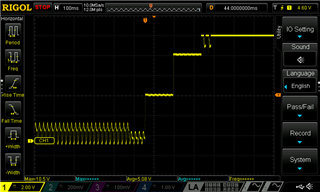
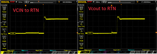
I recently designed a PoE Powered Device (PD) using the TPS2373-4. When I connect my PCB to a Power Sourcing Equipment (PSE), I observe an initial voltage of around 4.6V, but after that, nothing happens. It seems like the PSE is not detecting the PD. I've checked all the connections around the DEN pin, and everything appears correct. I’ve tried changing the DEN resistors to 24.9K, 27.6K, and 25K, but there’s no difference. However, when I daisy chain it with another PoE PD, the setup works perfectly, and I get the expected power output. Currently, I'm using a PoE Mode  A PSE. Can you identify any issues in this schematic? Any assistance would be greatly appreciated.


Thanks

Shrawan

  • Hi Shrawan,

    Thanks for reaching out!

    It may be related to the startup failure caused by VC_IN and VC_OUT.

    Do you have a down stream circuit and external voltage source to charge VC_IN (such as a DC/DC converter transformer AUX winding, it would be helpful if you can share the circuit if yes)? If not, you may need to add a circuit like below to make start up success. 

    Best regards,

    Diang

  • Hi Diang, 
    Thank you for your response.

    Yes, VCIN is powered via the transformer AUX winding. I've attached the schematic for reference. I also compared the startup sequence of my faulty PCB with the evaluation board using an oscilloscope. Could you identify the issue? I suspect it may be related to the initial detection phase, though I could be mistaken.

    This is my first design of a PoE module, and I aimed to create a compact, modular form factor, which may have led to some compromises in PCB isolation. However, when daisy-chained with other off the shelf PoE units, everything appears normal.

    Your input would be greatly valued.


     PD_detected_evaluation BoardPD_ not detected Faulty PCB

    Regards,
    Shrawan

  • Hi Shrawan,

    Thanks for your information. 

    You may tie the the MPS_DUTY with VSS. 

    Besides, could you measure the below voltages? 

    Best regards,

    Diang

  • Hi Diang, 
    Thank you for your response.

    I have checked the voltages at VCIN and VCOUT, and they are only reaching up to 512 millivolts at their highest. Also, connecting MPS_DUTY directly to RTN/VSS didn't make any difference.

    When I daisy chained my PCB with off the self working (PoE)device, both VCIN and VCOUT in my PCB shows about 12.5 volts.

    Also, I thought the issue might be with the TPS2373-4RGWR chip, so I replaced it with  IC from the working PoE module, but the problem remains same.

    Now, I'm starting to get little nervous. Confused

    I've also measured the DEN voltage, which peaks at 0.57 volts and averages at 0.354 volts. Is this normal?

    For your reference, PSE detection signature voltage is around 2.54V average with peak 4.36V but when I connect my PoE PCB voltage drop to peak 2.84v and average of 0.94V.

    Also, I supplied 5V DC to 1P12 and 1P36, current leakage/consumption was around 150-250uA. 

    Best Regards,
    Shrawan

  • Hi Shrawan,

    Thanks for your updates. Sorry that I got quite busy recently. I will try to get back to you by this week.

    Best regards,

    Diang

  • Hi Shrawan,

    Sorry that my last message is not very clear. For the voltage measurement, besides VC_IN, VC_OUT, could you also get the RTN-VSS voltage as the green line in that waveforms? 

    When you have 5V DC to 1P12 and 1P36, the current should be around (5V-1V) / 25k = ~160uA, where 1 V is voltage drop at the diode rectifiers (U1 and U2), while ~140 - 230 uA could be possible depending on the components selection. RTN-VSS waveform will help to observe if detection is passed. 

    Besides, have you tried to short PS_DUTY with VSS? And can you show me the termination circuit? Sometimes there are too much capacitance added for the termination circuits and caused the overall Cdet between VDD-VSS higher than 0.12 uF.  

    Best regards,

    Diang

  • Hi Diang,

    I really appreciate your time in helping me. 

    Below image is voltage waveform of RTN-VSS and DEN-VSS. 


    Yes I tried shorting MPS_DUTY to VSS did not change the behavior. Below image is the termination circuit i have used to test this PCB. 

    Also, One thing i noticed when I was daisy changing with working PoE is if i connect all 4 pairs both PoE module doesn't work. If I connect only 1P12 and 1P36 during daisy chain all works fine. 

    Best Regards,
    Shrawan

  • Hi Shrawan,

    Thanks for your reply.

    Get busy now and I will get back to you in 5 business days. 

    Best regards,

    Diang

  • Hi Diang,

    I think I found the problem. TVS Diodes D2, D3, and D4 are listed as bi-directional  in the BOM. Therefore, I didn't consider polarity when debugging. Unfortunately, our procurement team purchased unidirectional tvs diodes. D2 and D3 have the correct polarity, whereas D4 has reverse polarity. Once I removed D4, everything worked fine. On a new, fresh PCB, I only removed that diode without altering any other components, and everything worked as expected.

     I am really sorry for wasting your precious time. I was very focused on the DEN and classification stage, so I got distracted by the rectification IC other nearby passive component.

    I really appreciate your time; I couldn't have learned more details about PoE if it weren't for this issue and your support/direction.

    Best Regards,
    Shrawan