- Ask a related questionWhat is a related question?A related question is a question created from another question. When the related question is created, it will be automatically linked to the original question.
Tool/software:
Hi
I have been reviewing the datasheet of the TPS61033DRLR, and I have a question about VIN and VOUT.
In our application, the VOUT is set to be within the range of 4.826V to 5.174V base equation 1 in page 11.
※include ripple and Load Transient
When the input voltage VIN is approximately 5.1V,
could TPS61033DRLR achieving the VOUT range( 4.826V to 5.174V)?
I can not well understand
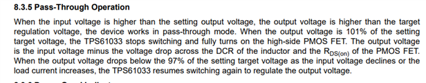
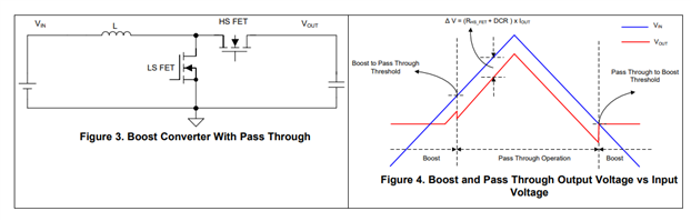
Pass-through mode when VIN > VOUT
in the 1 Features in page 1.
Thanks and Best Regards
Chunli