- Ask a related questionWhat is a related question?A related question is a question created from another question. When the related question is created, it will be automatically linked to the original question.
Tool/software:
Good Morning,
I contact you to have some information about the LMZ14203 behaviour in short-circuit.
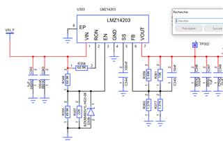
We impleted this component to generate two output voltage level : a 3V3 and a 5V from a single supply in range [8V;30V].
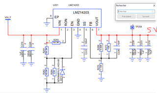
Schematic 5V :
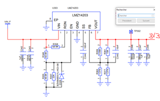
Schematic 3V3:
In our short-circuit test, we checked the current waveform on the output.
We were surprised to see different behaviour between the 5V output and the 3V3 output.
Here are the oscilloscope screen :
P5V : (Voltage in blue and current in purple)
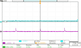
We though that this screen is a good functionning with low output voltage and some repetitively low current spike which mean the component try to check if the Short-circuit is still present.
P3V3 (in green voltage and in purple Current):
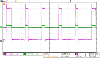
On this test, we see large current spike with remaining voltage.
In fact, we don't see it on this screenshot but the first spike seems to have the same behaviour as with the P5V.
All the following spikes are like the figure above.
During this test, the Input voltage of the component is stable. Same configuration of test are used for both capture above, a direct short circuit.
We wanted to ask you if you have an idea why this behaviour happened ?
How is managed the shortcircuit protection ?
Thank you for your help,
With best regards,
Olivier EMANUELY
Hi Olivier,
I will check and get back to you by tomorrow EOD (IST).
Regards,
Arpita
Hi Olivier,
Could you please share zoomed in waveforms of FB pin and Inductor current for debugging? Please refer to datasheet section "7.3.3 Current Limit" for short circuit protection feature.
Regards
Arpita
Hello Arpita
Unfortunately, the inductor is integrated in the component so i can't measure current flowing throw the inductor.
The Feedback voltage will only be a fraction of the output voltage (green curve on the screen above).
Approximatively: Vfb = 0.24*0.15 = 30mV
With regards,
Olivier
Hi Olivier,
Regards
Arpita
Hello Arpita,
The 5V (4.93V) :
The 3V3 :

HEllo Arpita,
Here are the capture. See that in comparison between the P5V and P3V3, I took same scale in axis. Behaviour is totally different between the two.
Note that i measured Vin, and it is a stable 29V.
Note also that there is electronic on the 3V3, there is a consumption of 300mA in output before the short circuit. There is nearly nothing in output of the 5V (approx 10mA).
P3V3 behaviour :

Zoom :
P5V behaviour :

Zoom:

Hello Olivier,
Please provide the below information for better understanding. How are you shorting the output terminals in P5V case? Are you shorting using electronic load? The P5V case waveforms shows Vout has two level, 5V and 2V. Vout is expected to be lesser than these levels when output terminals are shorted.
Are you shorting the output in pulsating manner like shorting the output for nearly 0.35ms and removing the short circuit for rest of cycle i.e. 1.65ms, and repeating the pattern?
Regards
Arpita
Hello Arpita;
Happy new year !
I shorted with a cable between P3V3 and GND (like the P5V to GND). That is continuous and passive (no electronics).
Regards,
Olivier
Hi Olivier,
If you are shorting output so the Vout and Vfb must be zero. Can you please share the setup picture? You can try with an electric load also.
Regards
Arpita