This thread has been locked.

If you have a related question, please click the "Ask a related question" button in the top right corner. The newly created question will be automatically linked to this question.

TPS62876-Q1: revier schematic and replacement frequency, does the circuit need to be adjusted?

Part Number: TPS62876-Q1
Other Parts Discussed in Thread: TPS62874-Q1

Tool/software:

Hi,

Please help to deal with the following materials and products. 

1.    1_6T OSFP AEC MARVELL LEO project, customer wants to review power supply design schematics;

2.     For the 800G project, please help review the PMIC related schematic diagram.

1_6T OSFP AEC MARVELL LEO Regulators.pdf      800G_AEC_OSFP_Volex design PMIC review.pdf

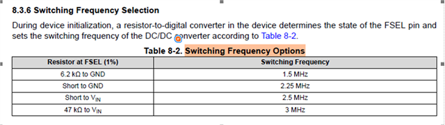
3.  In addition, there is a problem, the switching frequency of the following TPS62876-Q1 datasheet can be configured through hardware, please confirm whether the circuit needs to be adjusted if we need to change the frequency in the subsequent debugging process? Is it stable after frequency change? Do I need to do additional tests?

Thanks~

  • Hello Gao,

    I will provide a review of the schematics and layout later this week,

    Regarding question 3: I do not fully understand. What frequency is your application targeting? What do you mean with changing frequency?
    The frequency setting by external resistors is read during startup only.

    Regards, Werner

  • Hi Werner,

    Thanks for your reply!

    Regarding question 3:I mean, will the frequency need to be changed in other projects in the future, and does the hardware circuit need to be adjusted? Is it possible to use the original circuit design? Will it be stable? Do we need to test it?

    Thanks~

  • Hi Rhea,

    The schematics look good, I found not issues. To fully evaluate the chosen compensation values, please provide the exact part number of the used inductors and the requirements for load transients. Given the application, I suspect the chosen values are okay.

    The TPS62876-Q1 is capable of 25A Iout. These power lines draw a maximum of 10.14A. Why is the customer not using a lower rated converter? The TPS62874-Q1 provides 15A, for example, and is pin compatible.

    Also, what is the reason in the 1.6T schematics to use two parallel devices (total maximum output: 50A) to drive a rail with Imax = 9.95A?

    Regarding Q3:

    If the customer wants to change the frequency, it is possible the compensation values and Vout need to be adjusted, depending on the load transient requirements. The datasheet, section 10.2.2, shows that the calculation is depending on fsw.

    Regards, Werner

  • Hi Werner,

    Thanks for your support!

    Customer feedback as follows:

    Rhea:Inductors have been updated, L4/L87/L88--XGL4020-111MEC, L89--SRP2012TMA-R22M. The latest schematic design and inductor specifications are attached. Accurate load transient data is not currently available.

    please provide the exact part number of the used inductors and the requirements for load transients

    Rhea:The current maximum operating current is an estimated data and is not precise, the design needs to leave enough margin. What are the possible risks if we use a converter with a higher rating?

    The TPS62876-Q1 is capable of 25A Iout. These power lines draw a maximum of 10.14A. Why is the customer not using a lower rated converter? The TPS62874-Q1 provides 15A, for example, and is pin compatible.

    Rhea:Consider heat dissipation and use two parallel devices to reduce temperature rise.

    what is the reason in the 1.6T schematics to use two parallel devices (total maximum output: 50A) to drive a rail with Imax = 9.95A?

    Rhea:According to the current design, without adjusting the inductance and output capacitance, what is the effect of changing the operating frequency on the operating performance, and is it only necessary to adjust the compensation capacitance and compensation resistance at the COMP pin?

    If the customer wants to change the frequency, it is possible the compensation values and Vout need to be adjusted, depending on the load transient requirements. The datasheet, section 10.2.2, shows that the calculation is depending on fsw.

    Looking forward to your reply! 

  • Hi Rhea,

    What are the possible risks if we use a converter with a higher rating?

    There are no risks. Thank you for providing the feedback.

    Compensation is depending on the switching frequency and Cout. This is important for applications with high load transient requirements. This application usually has more relaxed transients, so I assume that the frequency can be changed easily. The system stability should be tested after changing frequency to determine if different COMP pin configurations are needed.

    Regards, Werner

  • Hi Werner,

    Thank you for your patient response!

    Attached is power supply design and PCB layout of 1_6T OSFP AEC MARVELL LEO, please help review.

    1_6T OSFP AEC MARVELL LEO Regulators 20250303.pdf            1600G_AEC_OSFP_20250304.brd     

    In addition, we also want to understand how the current of the two Pmics is distributed in stack mode. Modules operate in different states, the required current will be significantly different, is the current provided by the two Pmics roughly the same in all states?

    Thank you very much!

  • Hi Werner,

    Is there any update?

    Looking forward to your reply?

  • Hello Rhea,

    I will review the updated files later this week.

    Regards, Werner

  • Hello Werner,

    Looking forward to your reply!

    Thanks~

  • Hi Rhea,

    I checked the schematic and it looks good. :)

    For the layout I only have a few suggestions:

         1. Please make the layout symmetrical if possible, like in the datasheet.

         2. The compensation circuit for the device on the right might be far away from the device. Please try to put it as close to the device as possible.

         3. Please try to connect the analog GND for both devices if possible.

    All the suggestions above help to reduce the impact of noise. I see the room is very limited in the layout, so please just try to follow as much as possible.

    Besides, the current provided by the two BUCKs are roughly the same.

    Hope this answer can help.

    Best regards,

    Jingyi

  • Hi Jingyi,

    Thank you very much for your reply, it is very timely!

    Thanks~

  • Hi Rhea,

    You're welcome. Slight smile

    Thank you and best regards,

    Jingyi

  • Hi Jingyi,

    Please kindly help to check the revised layout again. The first suggestion cannot be completely symmetrical due to space limitation, and other suggestions should be modified. Please Double check.

    1_6T OSFP AEC 20250319.zip

    Thank you!

  • Hi Rhea,

    The layout looks good to me now. :) 

    Thank you and best regards,

    Jingyi