This thread has been locked.

If you have a related question, please click the "Ask a related question" button in the top right corner. The newly created question will be automatically linked to this question.

TPS23754-1: Regarding TPS23754-1(TPS23754PWPR-1) 802.3at POE issue

Part Number: TPS23754-1
Other Parts Discussed in Thread: TPS23754, PMP6812, PMP22301, TPS23754EVM-420, PMP10288, PMP9563, TPS23754EVM-383

Tool/software:

Hi Sir,

We had designed  a TPS23754-1(TPS23754PWPR-1)  802.3at POE WAPAX09 project before. The project is a WiFi AP product.

Recently, we had reported to TW FAE/ Ian Wang and  discussed by email regarding TPS23754-1 POE detection fail issue 

Since TI TW FAE/ Ian Wang mentioned, to aovid TPS23754-1 PD turning off, he suggested the C646 cap value range should be 33~47uF for 25W application design. Attached is WAPAX09 TPS23754-1 schematic for your reference that C646 is highlighted.

Thus, we have below questions. Please help.

1. We would like to know WAPAX09 TPS23754-1 schematic is referred which TI TPS23754-1 HDK reference design version.

Please help to advise the TI TPS23754-1 HDK reference design version and schematic for us.

2.According TI TW FAE/ Ian Wang information regarding  C646 cap value range, how can we calculate the C646 cap value in  TPS23754-1  802.3at POE ? Please help to provide detail equation and document for us.

3.Which test items and signal waveforms we have to measure and perform for TPS23754-1 802.3at POE schematic in H/W evaluation stage? Then, we can avoid the TPS23754-1 POE detection fail issue happened or the schematic design margin is not enough.

Please help to advise.

thanksWAPAX09_TPS23754-1_POE detection_issue20250225.pptx

  • Hi shermen,

    PoE team is doing internal validation tests and the reply on E2E may be delayed for 3 - 5 business days. Sorry for the delay and thanks for your patience.

    Best regards,

    Diang

  • Hi Shermen,

    1. Below is the reference we shared about TPS23754. If your circuit is flyback it could be PMP6812.

    Reference

    Topology

    PD

    Vout

    Iout

    PMP6812

    Flyback

    TPS23754 

    12

    1.8

    PMP6672

    Flyback

    TPS23754 

    5

    5

    PMP22301

    Flyback

    TPS23754

    24

    0.9

    TPS23754EVM-420

    Flyback

    TPS23754

    5

    5

    PMP10288

    AC forward

    TPS23754

    3.3

    7.2

    PMP9563

    AC forward

    TPS23754

    12

    2.5

    TPS23754EVM-383

    AC forward

    TPS23754

    12

    2.5

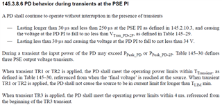
    2. Using I=Cdv/dt with I=25.5W/42.5V=0.6A, dv=42.5-36=6.5V and dt=250usec results in C=~23.1uF.

    Power Bulk Cap
    13W 10-22uF
    25W 33-47uF
    50W 68-100uF
    70W 100uF-200uF

    25.5W 推薦33-47 uF. 22uF 比較worst的250us 0-current transient不行,但99.9%的情况影響不大。


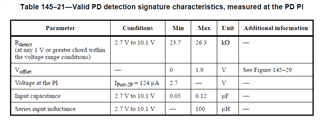
    3. If the PD cannot pass the handshake, can you double check all caps between VDD-VSS is less than 120nF? And could you share the waveforms including the PD's VDD-VSS voltage and current in power interface?

    If the PD is connected then power off, it may be related to the loss of maintain power signature. Could you try with a load > 1W?

    Best,

    Diang

  • Hi Diang,

    From your reply information, we download PMP6812 reference schematic to check.

    We find the C22 value of PMP6812 schematic is 22uF. It is same as C646 value of our WAPAX09 schematic.

    BTW, in our WAPAX09 schematic, we add an extra cap 22uF and parallel with C646 (22uF) and reported to customer. Adding an extra 22uF cap can solve the detection issue.

    Please refer to attached file for detail that we are highlighted.

    WAPAX09_TPS23754-1_POE detection_issue20250304.pptx

    Why the cap value is 22uF in TI reference design? Would you help to explain? Our customer is asked this question.

    Please help to advise

    thanks

  • Hi shermen,

    PoE team is doing internal tests and the reply on E2E may be delayed for 3 - 5 business days. Sorry for the delay and thanks for your patience.

    Best regards,

    Diang

  • Hi Sir,

    Regarding the  C646 (22uF)  capacitor value, we check the cap datasheet again. And we find there has a DC bias v.s. Cap value characteristic curve. Please refer to attached file for detail.

    According the curve, the cap value varies rapidly when the DC voltage is at 12V for TPS23754-1 application.

    Since the capaciotr characteristic, please help to advise whether it has any impact on this TPS23754-1  POE circuit.

    Please help.

    thanks

    TPS23754-1_PSE voltage transient to PD and 22uF cap characteristic question20250306.pptx

  • Hi shermen,

    Thanks for your follow up.

    PoE team is doing internal tests and the reply on E2E may be delayed for 3 - 5 business days. Sorry for the delay and thanks for your patience.

    Best regards,

    Diang

  • Hi Shermen,

    The 22uF C22 is the VC cap. It is related to the PWM control IC and start up delay time. 22uF electrolytic cap normally is enough for a proper inrush delay time. A ceramic cap may have DC bias which could has effective lower cap when voltage is high. 

    The 47uF C11 is the cap we did the calculation about the 250 us transient time. It normally need electrolytic cap too. 

    25.5W 推薦33-47 uF. 22uF 比較worst的250us 0-current transient不行,但99.9%的情况影響不大。

    Best regards,

    Diang

  • Hi Diang,

    As you mentioned,  the C22 value is 22uF in TI PMP6812 schematic and C11 is 47uF.

    From FAE/ Ian and you said that "25.5W 推薦33-47 uF. 22uF 比較worst的250us 0-current transient不行,但99.9%的情况影響不大。"

    We think you mean  25.5W 推薦33-47 uF cap value, the cap designator is C22. Is it correct?

    Why do you mention C11 47uF?

     Our WAPAX09 schematic is follow TI PMP6812 schematic to design.

    Please advise

    thanks

  • Hi Diang,

    We have an importnat question for  C22 cap value is 22uF in TI PMP6812 schematic reference design.

    Our customer is asked why TI PMP6812 schematic reference design is adopted 22uF.

    Our WAPAX09 schematic is followed TI PMP6812 schematic to design, so we also adopt 22uF (locator:C646) in our WAPAX09 schematic. Please help to explain the reason why the cap value is 22uF in TI PMP6812 schematic  reference design.

     We need to reply customer the reason for TI PMP6812 schematic is 22uF (locator:C22) as well.

    Please help.

    BTW, please proivde you wechat contact information, we would like to discuss with you by wechat. Can you provide?

    thanks

  • Hi shermen,

    Thanks for reply. We will take a look and get back to you in 3-7 business days. Thanks for your patience.

    Best regards,

    Diang

  • Hi Shermen,

    Thanks for your patience.

    For C11 = 47uF or 22uF

    From FAE/ Ian and you said that "25.5W 推薦33-47 uF. 22uF 比較worst的250us 0-current transient不行,但99.9%的情况影響不大。"

    Yes this is for the C11: 33-47uF is recommended to fully compliant with standard. But 22uF in most of cases can be fine.

    For C22 = 22uF 

    PD needs to have a >80ms inrush delay. It is mainly the total timing of inrush timing delay + DC/DC soft startup delay. 22uF is for adjusting the inrush timing delay, which is 44ms - 158ms (22uF is Electrolytic cap in the test). If your DC/DC soft startup delay is long and the startup current is less than 0.4A, you can use smaller C22. 

    Best regards,

    Diang