This thread has been locked.

If you have a related question, please click the "Ask a related question" button in the top right corner. The newly created question will be automatically linked to this question.

TPSI2140-Q1: Internal MOSFET Ratings

Part Number: TPSI2140-Q1
Other Parts Discussed in Thread: TIDA-010232

Tool/software:

Hi Team,

What is the absolute maximum voltage rating of the device that can handle between S1-S2?

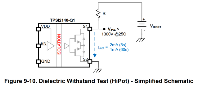
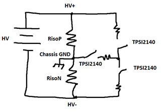
Find attached snapshot of our resistor network circuit with TPSI2140, by applying 3kV we have observed 13mA of leakage current.

Is it due to the leakage current of the internal MOSFETs?

Please let us know for 3kV hipot signal how much will be the voltage between S1-S2, in our reference circuit. As absolute maximum data is not provided in the datasheet.

Regards,

Parth Bhavsar

  • Hello Parth,

    Thanks for reaching out to our team on E2E. I assume you are doing HiPot/withstand voltage testing where you are applying 3 kV for 60 seconds from DC+ to GND_EARTH. R needs to be sized to limit avalanche current (IAVA) to 1 mA. It sounds like the TPSI2140 in your circuit may already be damaged due to overheating. For 3 kV test, we recommend R = 1.7 MΩ

    HiPot/Withstand Voltage

    (VHIPOT - VAVA) / R = IAVA

    R = (3 kV - 1.3 kV) / 1 mA

    R = 1.7 MΩ.

    Are you doing any EMI or ESD testing next? If so, you may consider adding capacitance across the device.

    EMI

    If you are doing EMI testing and needs to pass CISPR25 Class 5, we recommend adding capacitance across TPSI2140-Q1 to provide a return path for the noise sent across isolation as shown in diagram below (in ESD section).

    ESD

    If you are doing ESD testing with voltages > 5 kV, we recommend adding capacitance across TPSI2140-Q1 to limit voltage seen across the device as shown in diagram below. Attached slides for more information.

    ESD Summary.pdf

    Best regards,
    Tilden Chen


    Solid State Relays | Applications Engineer

  • Hi Tilden,

    Thanks for the feedback.

    In our design we have used this circuit for Isolation monitoring as per the TIDA-010232. So, as per your suggestion if we change the value of resistors then it may be affect on the isolation monitoring resistance measurement accuracy at lower voltage rating (~200VDC).
    Our design is rated for the 1000VDC, and as per the UL2231-2 Hipot/withstand voltage test applicable voltage is 2 X Rated Voltage of the system. 

    What is your suggestion on this other than changing the value of resistance and need to pass the Hipot test with 3kV?

    Regards,

    Parth Bhavsar

  • Hello Parth,

    Thanks for your reply. I understand that changing the resistance values may affect measurement accuracy. The intention of increasing resistance is to reduce current to limit the device power dissipation. The other variable we could limit is voltage in order to maintain similar resistance, maybe adding a third TPSI2140 to chassis GND.

    If your HiPot test applies 3 kV for 60 sec from HV+ to Chassis GND and HV- to Chassis GND independently, then series R for each can be 400 kΩ.

    If your HiPot test applies 3 kV for 60 sec from HV+ to Chassis GND and HV- to Chassis GND simultaneously, then series R for each can be ≥800 kΩ.

    Best regards,
    Tilden Chen


    Solid State Relays | Applications Engineer