This thread has been locked.

If you have a related question, please click the "Ask a related question" button in the top right corner. The newly created question will be automatically linked to this question.

TUSB544: Intermittent Display Issue in USB-C to DisplayPort Design

Part Number: TUSB544
Other Parts Discussed in Thread: TIDA-01620

Tool/software:

Dear TI Team,

We have designed a USB-C to DisplayPort adapter board using the TUSB544. While DisplayPort Alternate Mode negotiation appears to complete successfully and the TUSB544 switches the signals as expected, we are encountering a persistent issue: the external monitor stays black most of the time, and briefly displays the image for about 0.5 seconds at random intervals before going black again. Over a period of 10–15 minutes (without touching the board or cables), we typically observe about 5 image flashes.

Here is a summary of our setup and observations:

  • DP Alt Mode negotiation is verified using a Power Delivery analyzer.

  • The HPDIN pin is held high (3.3 V). We force it via I²C (register GENERAL_4, bit 3: HPDIN_OVERRIDE). The HPD pin of the DP connector is connected to HPDIN, and we measure a stable 3.3 V.

  • The TUSB544 configuration appears correct — we can read the display's EDID, and when the image is briefly shown, it is clear and of good quality.

  • Hardware configuration:

    • 30 cm USB-C cable (PD compatible) between the host PC and our board

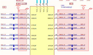
    • 9 cm PCB trace length between the USB-C and DP connectors

    • 50 cm DisplayPort cable between the board and the monitor

  • Differential pair routing rules followed:

    • 100 Ω ±10 % differential impedance

    • Intra-pair skew ≤ 0.127 mm (5 mils)

    • Inter-pair skew ≤ 2.54 mm (100 mils)

    • Clearance between pairs: 3W (3x trace width)

    • Shielding vias placed between differential pairs

  • Under Linux (i915 driver), we observe:
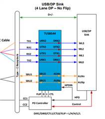
    • 4 active lanes

    • 2.7 Gbps

    • Link status: GOOD

  • From the DPCD registers, we confirm for lanes 0–3 (0x202 and 0x203):

    • CR_DONE = 1

    • CHANNEL_EQ_DONE = 1

    • SYMBOL_LOCKED = 1

  • However, we observe very high symbol error counts in SYMBOL_ERROR_COUNT registers (0x210 to 0x217), often showing 0xFF or near-maximum values.

We have tested numerous DRX/URX EQ settings, but without significant improvement.

We currently lack access to a high-speed oscilloscope or protocol analyzer capable of eye diagram measurements, which limits our ability to inspect DP signal quality at the physical layer.

With your expertise, could you help us identify the most probable root cause of this issue — namely the brief, random flashes of valid image, with the screen remaining black the rest of the time?

Thank you in advance for your support.

Best regards,

Clément

  • Hi Clement:

        Did you use DP connector on output? TUSB544  is best used  for type-C connector.

       Can you send schematic for review first?

    Regards

    Brian

  • Hi Brian,

    Thank you for your quick reply.

    Yes, we using a DisplayPort receptacle on the output side of our board.

    We wasn’t aware that the TUSB544 is primarily intended for USB-C to USB-C applications.

    We based our design on the TIDA-01620 reference design, which uses the TUSB544 between a USB-C connector and a DP connector.

    Please find attached the schematics of the USB-C connector, the TUSB544, and the DP connector.

    Regarding the TUSB544 schematic, it is intentional that RX2 is connected to URX1, TX2 to UTX1, etc.. We made these choices to optimize PCB routing, and we’re using bit 2 (FLIPSEL) of the GENERAL_4 register to reorder the signals correctly via I²C.

    Let me know if you need any additional information about our design.

    I’ll continue running tests on my side and will update you if I manage to identify the cause of the issue.

    Thanks again for your support.

    Best regards,

    Clément Perrin

    5047.USB-C_CONNECTOR_SCHEMATIC.pdf
    3755.TUSB544_SCHEMATIC.pdf
    3755.DP_CONNECTOR_SCHEMATIC.pdf

  • let me review schematic first.

    Best

    Brian

  • Sure, no problem.

    I already shared the schematics in my previous message, but I'm attaching them again here just in case :

    8037.USB-C_CONNECTOR_SCHEMATIC.pdf
    1104.TUSB544_SCHEMATIC.pdf
    8546.DP_CONNECTOR_SCHEMATIC.pdf

    Best regards,

    Clément

  • Hi Clément:

    your schematic didn't match the channel mapping in datasheet.

    Best

    Brian

  • Hi Brian,

    Thank you for your quick response and for reviewing the schematic.

    You're right — the lane mapping does not fully follow the datasheet. Here's how I understood the behavior of the TUSB544, and I would appreciate your clarification on any misunderstanding :

    • Since the PC provides the DisplayPort signal, I assumed the DP lanes enter through the upstream port of the TUSB544. I configured the chip in USB + DP Alt Mode (Source), with 4 lanes enabled.

    • To simplify routing, I connected the signals as follows:

      RX1 → URX2 → DRX2 → DP0
      TX1 → UTX2 → DTX2 → DP1
      TX2 → UTX1 → DTX1 → DP2
      RX2 → URX1 → DRX1 → DP3

    I thought there was no distinction between URX and UTX, so I did not strictly pair RX1 to URX1, TX1 to UTX1 etc...

    • This routing aligns with a pin assignment C or E in Flip mode, so I enabled the FLIPSEL bit.

    • Since USB-C cable is in No Flip for my tests, I forced AUXP to SBU1 and AUXN to SBU2 using the AUX_SBU_OVR bit.

    • Your review made me realize that my configuration, using a USB-C to USB-C cable between two receptacles, is more compatible with DP Sink mode.

    • I wasn’t aware that USB-C cables cross TX and RX (TX <--> RX).

    • I initially based my design on the TIDA-01620, but that uses a direct USB-C plug, not a cable between receptacles.

    So, taking the example of the USB + DP Sink No Flip configuration, we should have the following lane mapping:

    TX1 → URX2 → DRX2 → DP3
    RX1 → UTX2 → DTX2 → DP2
    RX2 → UTX1 → DTX1 → DP1
    TX2 → URX1 → DRX1 → DP0

    Considering the internal TX/RX crossing, my current routing actually results in:

    TX1 → URX2 → DRX2 → DP2
    RX1 → UTX2 → DTX2 → DP3
    RX2 → UTX1 → DTX1 → DP0
    TX2 → URX1 → DRX1 → DP1

    Indeed the lanes are reversed, this might explain the brief image flashes we observe.


    However, even when testing with only 2 lanes active (either DP0/DP1 or DP2/DP3), I still don’t get a stable image, and I can’t explain why.

    I now have three questions:

    1. Can you confirm that a USB-C to USB-C cable crosses TX and RX?

    2. What is the difference between DP Sink mode and DP Source mode in the TUSB544?
      From what I can see, the only change seems to be the positioning of the lanes ML0, ML1, ML2, and ML3 between the URX/UTX and DRX/DTX ports.
      Is there any other functional difference? Because it seems that with the right SWAP configuration, one can switch from Source to Sink mode just by reassigning the channels.

    3. Are there any aspects of how the TUSB544 works that I may have misunderstood?
      If there are specific details or configuration principles I’ve overlooked, I would really appreciate your clarification.

    Thank you again for your help.

    Best regards,

    Clément

  • Did you use USBC cable on left (UTX/UTX0) and DP cable on right side (DTX/DRX), if yes, then TUSB544 should be configured as Sink application.

    Best

    Brian

  • Hello Brian,

    Thank you for your support — my board is now working perfectly.

    Indeed, I’m using a USB-C cable on the left side (UTX/URX) and a DisplayPort cable on the right side (DTX/DRX).

    I reconfigured the TUSB544 in DP Sink mode, which makes more sense for my use case. I based the configuration on Pin Assignment E in UFP_D mode for DP Alt Mode, and I also took into account that in a USB-C to USB-C cable, RX and TX lines are crossed.

    I also applied some equalization adjustments:

    • Upstream DC Gain: 0 dB

    • Downstream DC Gain: 0 dB

    • VOD Linear Range: 1100 mVpp

    • Upstream EQ Gain: 2.7 dB

    • Downstream EQ Gain: 2.9 dB

    Initially, I was testing with a display that required 4 DisplayPort lanes. Since the lane mapping was incorrect at that point, it explained the image “flashes” I was observing.

    Thanks to a multiplexer (used in the second part of my design), combined with various TUSB544 configuration options (notably the FLIPSEL bit), I was able to use only 2 correctly mapped lanes, allowing me to drive the 2 lanes DP Display used in my design.

    Thank you again for your time and support.

    Best regards,

    Clément