TPS2372: TPS2372 schematic review

Part Number: TPS2372
Other Parts Discussed in Thread: TPS2378

Tool/software:

HI Team

Can you help to review the schematic design?

Input:PoE 802.3af/at 37-57V, 25Wmax

Output:5V2A@802.3af5V3A/9V2.22A@802.3at

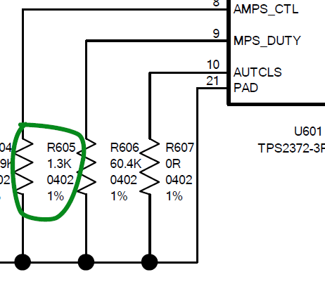
To identify the POE by TPS2378 T2P pin output voltage level to U603 pin1,when the voltage level is high,it is 802.3af ,if the voltage level is low,it is 802.3at

Power_Rev10.pdf

  • Hi Marry,

    Thanks for reaching out!

    I want to confirm the PD chip used is TPS2372-3, not TPS2378.TPH and TPL and be used to indicate AF (TPH=Hi-Z, TPL=Hi-Z) and AT (TPH=Hi-Z, TPL=Low). 

    Please see the comments on the PoE PD circuit only: 

    1. To enable the auto maintain power signature, AMPS_CTL needs a 1/4W or larger power rating at R605. Normally 1206 or larger. 

    To disable the auto maintain power signature, you need to DNP R605.

    2. In most of cases, autoclass function is not needed, unless the application is constant load like LED lighting. DNP R607 to disable autoclass function. 

    3. PG pin is recommended used to avoid downstream circuit draw too much current during PD inrush. 

    4. PC601 is optional to use 33uF to meet PoE longest 250us 802.3BT transient requirement. 

    5. Isolated DC/DC is optional to meet 802.3BT standard isolation requirement.

    Best regards,

    Diang

  • Hi Diang

    Thanks for your support. Customer is carrying out the prototype system test, there are two questions hope can get your support as the attachment 1.

    2&3&4 is the schematic and Gerber file of this design. 

    Can you help to analysis the reasons? Thanks!

    TPS2372 Support Needs.pptxTPS2372 Support Needs.pptxpower_ethernet_V13.pdf0777.PCB.pdfGaber File.zip

  • Hi Harry,

    Thanks for your updates. We will get back to you by this week. Thanks for your patience. 

    Best regards,

    Diang

  • Diang

    Can you help to prioritize this support? Customer will start to fabricate the 2nd version PCB, need TI's insight to avoid these two issues. And can you help to review the latest PCB design and give some feedback by today?

    Thanks!

  • Hi Harry,

    Please check the email from Allan Fan for two issues they mentioned in the slides.

    The PD stage schematic looks fine.

    Best regards,

    Zhining