UC3907: load sharing

Part Number: UC3907
Other Parts Discussed in Thread: UCC29002, UCC39002

Tool/software:

Hi ti team,

For the new project, we intend to use the UC3907 for load sharing, and design two 24V/3A POE power supplies to power a 24V/6A load.

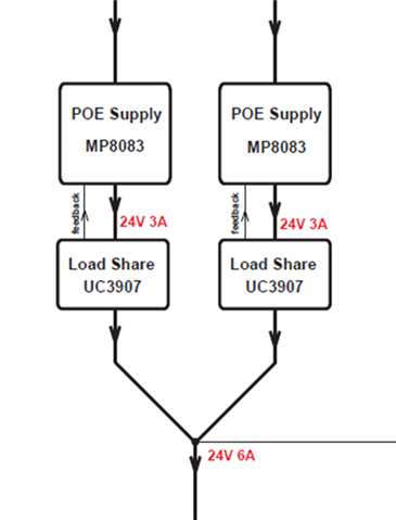
Could you please advise on how to ensure that each of the two POE supplies delivers an average current of 3A? Are there any reference circuits available? (As shown in the block diagram below

  • Hello Switch, 

    Thank you for your interest in load-sharing controller by TI. 

    The UC3907 is an old device made entirely in bipolar technology, and contains reference and feedback circuitry to be used for regulating the power supply. 
    If you plan on designing each POE supply discretely, then this device can work for you. 

    Limited technical support documentation can be found here: https://www.ti.com/product/UC3907#tech-docs 

    If you already have two previously-designed POE modules that you want to share the load with, then I recommend to use the UCC29002 controller, which is much simpler and newer.  It is made in BiCMOS technology for lower cost. 

    Extensive technical support documentation for this part can be found here: https://www.ti.com/product/UCC29002#tech-docs 

    Regards,
    Ulrich

  • Hi  Ulrich,

    The VDD voltage of the UCC29002 does not support 24V, and its maximum voltage is 15V. May I ask if we should use a voltage divider resistor to reduce the VDD voltage to within 15V?

  • Hello Switch, 

    The UCC29002 can accomodate sharing voltages higher than 15V by using its internal clamp (~13.5V).

    A single resistor is all that is needed to drop the ~10V needed between 24V output and 14V VDD level. 

    This Excel-based Calculator Tool can help select the appropriate resistor value, as well as the overall design: https://www.ti.com/tool/download/SLUC684 

    Regards,
    Ulrich

  • Hi Ulrich,

    I used the Excel Calculator Tools in the attachment to calculate the resistor/capacitor parameters. The attachment is the circuit diagram for the POE power supply + UCC39002; could you please help check it?

    Additionally, the schematic diagrams for the other POE power supply + UCC39002 are all the same. Can we achieve the average supply of the required output current for the two POE power supplies simply by connecting pin 7 of the two UCC39002 chips together?
  • Hello Switch, 

    Please make the changes shown in this mark-up of your schematic: 

    As I mentioned earlier, you don't need a resistor divider to VDD, you only need a pull-up.  The UCC29002 has an internal clamp at ~14.25V. 
    A 2kR from 24V can deliver ~5mA to VDD which is sufficient to support all the current requirements. 

    In the Excel file, in cell D39 you chose 1000000 for the Rsense of the "module", but in the schematic you have R149 = 200R.  
    Either set R149 = OPEN (infinite), or set R149 = 400R and R148 = 400R. 

    In the flyback part I should not be involved, but the transformer output current will have very large RMS, so I think you should have the big output caps after the diodes and the small output caps after the inductor for high frequency filtering.  You can do what you want, but that is my suggestion. 

    Regards,
    Ulrich

  • Hi Ulrich,

    If we modify the circuit according to your proposal (POE SUPPLY + UCC39002) and finally connect the 7th pin of the two UCC39002 chips together, can the circuit achieve current sharing and provide 3A current respectively?

  • Hello Switch, 

    Yes, that is how the UCC29002 (same as UCC39002, with wider temperature range) works. 
    Please read the UCC29002 datasheet which explains the details of this load-sharing operation.

    If you intend to change from UC3907 to UCC39002, I request to please close this thread and start a new one with UCC39002 in the title, so that the proper part number is tracked for support. 

    Regards,
    Ulrich