TPS65220: TPS6522053RHBR - no power from supply rails (AM64X)

Part Number: TPS65220
Other Parts Discussed in Thread: AM6442

Tool/software:

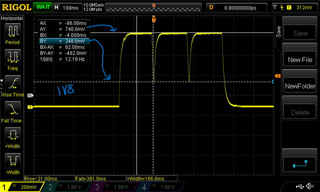
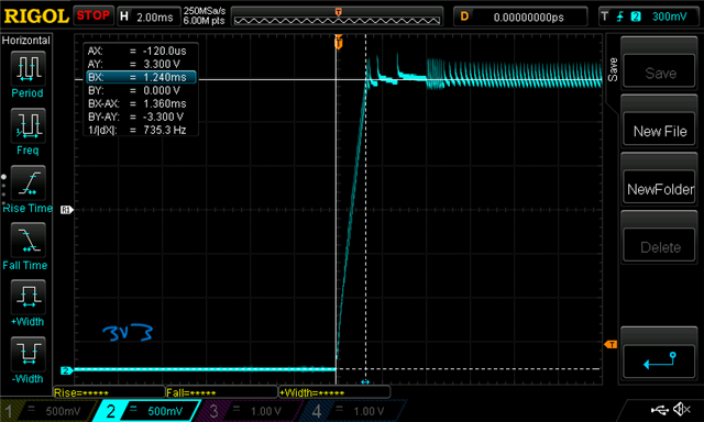
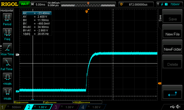
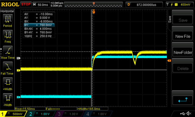
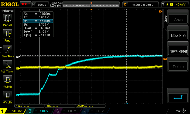
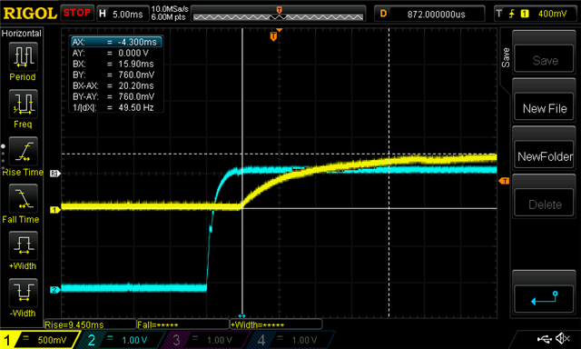
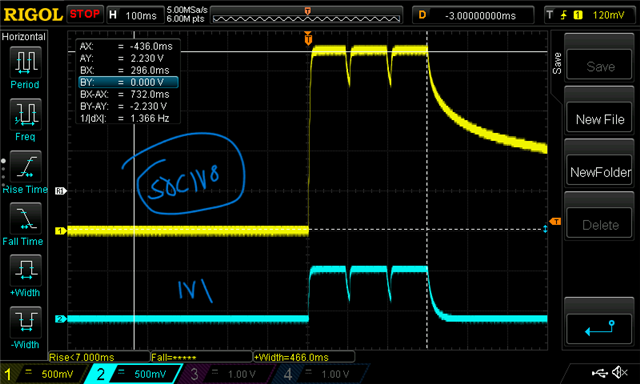
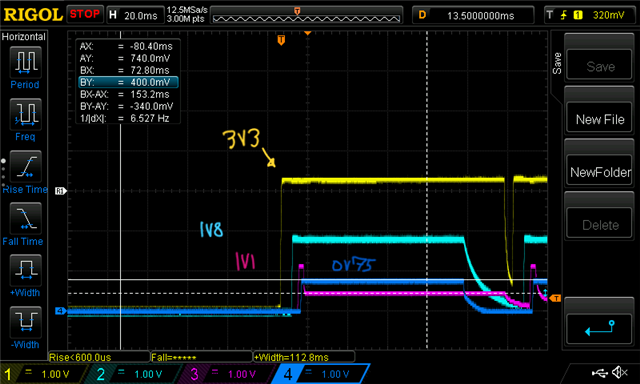
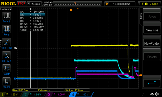
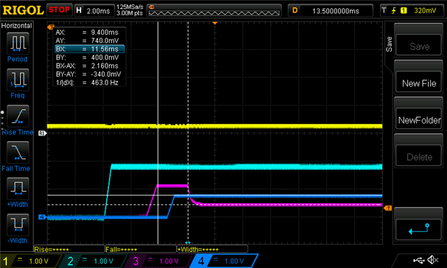
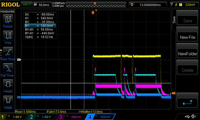
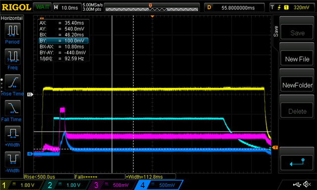
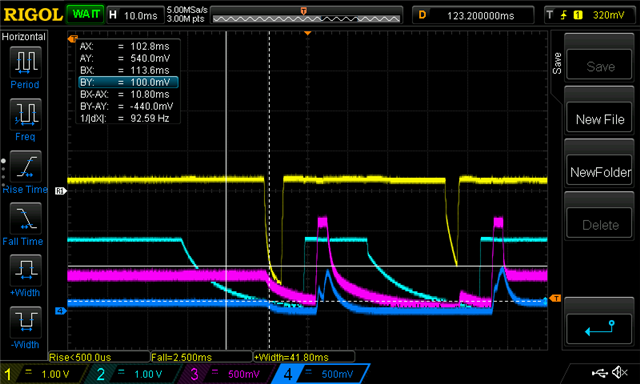
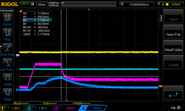
Hi all - I'm seeing that GPO2 is trying to turn on 3 times, but the power rails are not able to come completely up- after which it seems to give up until power removal/reapplication.

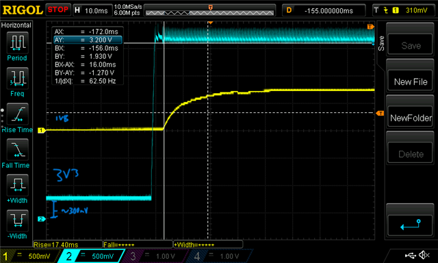
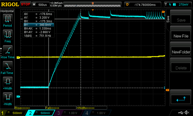
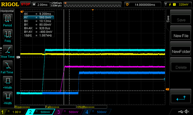
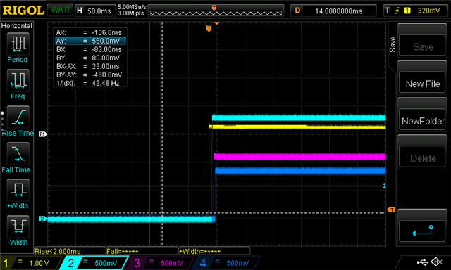
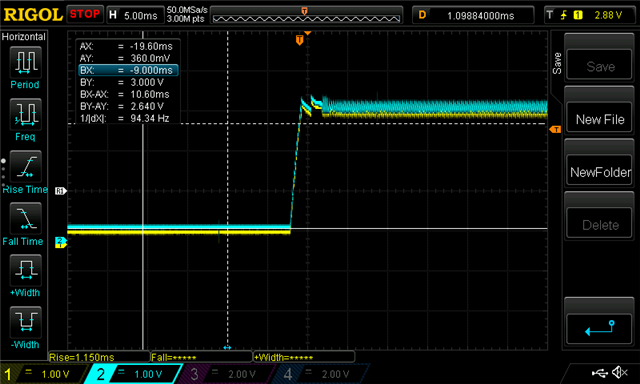
First scope shot is the 3v3 power rising, next is the power and EN rising, the remainder are the BUCK2 / LDO4/ BUCK3 / BUCK1 shown against VIN and GPO2. Measurements are at the pins of the TPS6522053 package.

My first thought would be whether or not this a matter of insufficient supply to the TPS6522053 (e.g. not enough capacitance at input) to keep the input from sagging below a UV lockout value?


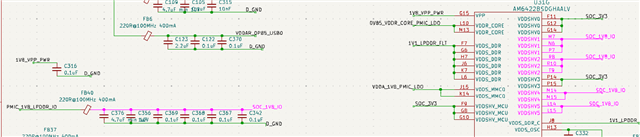
Schematic for TPS6522053


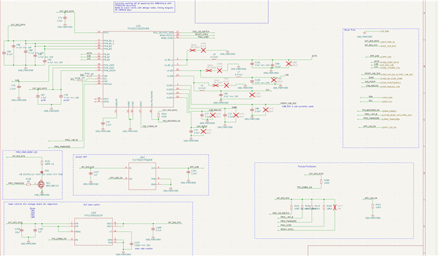
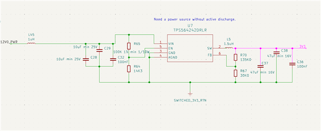
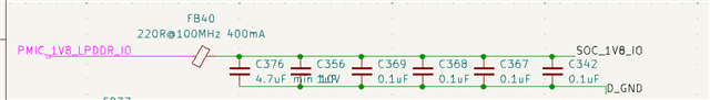
SMPS for 3V3 feeding TPS6522053


  • As a note - adding a 220uF electrolytic cap to the output of the TPS56424 does not seem to have made a significant difference in the TPS6522053 performance.

  • Hi James,

    Thanks for reaching out on E2E. 

    It looks like the device getting a fault, attempting to power-on again, and then hitting the third RETRY_COUNT which powers it down. 

    Are you using I2C in your system at all, and would you be able to read the interrupt registers to identify the source of the fault / confirm whether this is a VSYS UVLO fault? 

    Best Regards, 
    Sarah

  • The onboard I2C devices are powered by this - that said, I likely can jury rig a pico to connect to it somehow (unless you have a better idea :D).

  • As of yet, I'm not able to successfully get it to respond using I2C - I've unmounted the R158/R161 from the board, then attached to the pads connecting to the device, and pulled up the SDA and SCL lines to 3V3 using 4K7 resistors.

    Right now, using a pico with i2c.scan(), I'm not able to get an address; I'm also not able to directly access it at address 0x30.

    I've confirmed the connectivity to the pins via a simple resistance check, resistance to the supply, isolation from each other, and will likely grab an oscilloscope shortly to take a look at the signals (unless I get a message that I'm barking up the wrong tree, so to speak).

  • Doing a standard sanity check, it's always a good idea to make sure that grounds are equivalent - there was about a 2V difference between the pico and the MCU board - correcting that, I'm able to poke it via I2C.

    Register for Interrupt source (0x2B) reports 0x01 - which to my understanding means that the source is somewhere in timeout_RV; reading timeout_RV (0x32) gives 0x06 - which if reading correctly, would indicate some error with residual voltage on buck3/buck2 (the error here is not very clear from the descriptions in the table for the registry).


    Reading interrupt registers...
    INT_SOURCE       : 0b00000001
    LDO3/4  (UV/OC/SCG): 0b00000000
    LDO1/2  (UV/OC/SCG): 0b00000000
    BUCK3   (UV/OC/SCG): 0b00000000
    BUCK1/2 (UV/OC/SCG): 0b00000000
    SYSTEM  (HOT/WARM) : 0b00000000
    RESIDUAL VOLTAGE  : 0b00000000
    RV TIMEOUT→SD     : 0b00000110
    PUSHBUTTON        : 0b00000100

  • So if it was a residual voltage issue on the rails - my expectation would be that we would not attempt to turn on in the first place, so that we should not see the rails rising at all. I could very much imagine that there is a detection on the subsequent startups (e.g. attempt 2, attempt 3) - we definitely can see that we do not have full discharge on the buck2/buck3 outputs in the ~12ms or so that it is turned off prior to attempting again.

    I can check buck2/buck3 with an oscope with better/cleaner leads and ground and try to get a more accurate measurement of what the voltage is. I could also try to put some bleed resistors in for buck2/buck3 as well and see if that helps.

  • Hi James,

    Thanks for the detailed steps of your debugging process!

    It looks like the RV timeout from Bucks 2 and 3 are the only faults being flagged, 

    Do let me know if you are able to measure what value Buck2 is reaching before shutting down,
    I can't tell exactly from your earlier scope capture, but it doesn't appear to be reaching the full 1.8V ?

    Are you able to tell me the total capacitance values on the Buck 2/3 rails, including the local 47 uF cap?

    Best Regards, 
    Sarah

  • Hi Sarah, there is a total (face value, e.g. non-derated) of 73.7uF on the buck2 (1V8) rail; 96.1uF on the buck3 (1V1) rail - in terms of capacitors on those lines.
    It definitely wasn't reaching the full 1V8 or 1V1, it looked to be capping at about 700mV or so.


  • So the 1V8 peaks at about 740mV, dips to 248mV between attempts. The 1V1 peaks at about 616mV, and dips to about 200mV between attempts.
    I don't think adding bleed resistors is going to be helpful, but I'm willing to be wrong.
    The inductors are DFE201612E-R47M=P2 (https://pim.murata.com/en-eu/pim/details/?partNum=DFE201612E-R47M%23) - I don't think they would be going into saturation here.

    I suppose it could be current limiting? But would we not see the register for overcurrent?


  • Just for kicks, I pulled another (fresh) board and looked at the 1V8- this doesn't have the 220uF added to output of the TPS56424. 
    The peak and dip are pretty much the same - however the duration of these on-attempts is about half off that with a larger input capacitance towards the TPS6522053, and the rise time is certainly longer.


    The 1V8 has the following consumers: LPDDR4, AM6442, VCCQ for an EMMC, 3 level converters (3V3<->1V8 - SN74LXC1T14QDCKRQ1), some IO pullups, VIO for a WL1801MODGBMOCR, a ASDK2-32.768KHZ-LRT.
    I'm having a hard time conceptualizing that these would be pulling too much current, but it isn't impossible I guess.

  • Hi James, 

    I'm also in doubt of an overcurrent issue since the register wasn't flagged. 

    Are you able to somehow test a board with some 3.3V DC source rather than the TPS56424 output?
    Or are you able to test the operation of the PMIC with the loads disconnected?

    I find it strange that VIN from TPS56424 is also reactive to the fault dips.

    Are you able to provide a zoomed-in shot of VIN vs 1V8, particularly the initial ramp-up?
    I want to ensure VIN is fully powered up before Buck2 is attempting to power on, since a slow ramp on VIN + FSD enabled may cause a fault this way. 

    Best Regards, 
    Sarah

  • Hi Sarah - the first shots of both VIN (3v3) and BUCK2 (1V8) - grounding is good for the BUCK2 probe, but the VIN grounding wasn't great (we can see the offset) - that said, we should be able to get some idea of the timing of when the 1V8 ramps vs the 3V3 input. It looks like ~2ms from VIN reaching 3.3V until the 1V8 starts ramping up. I've added some shots only of the VIN ramping with good grounding, so we can look at that better as well.
    The 0-100% is roughly 1.4ms; the 10-90% is roughly 1.2ms - I would think that this should be more than fast enough. Nothing is particularly standing out to me as a particular issue there.
    It looks like the TPS56424 is shifting to a higher switching frequency when the TPS6522053 turns on for 1V8, and again when the 1V8 is off, which would be in line with the expectation that more load is "switched" onto the 3V3 line, no?

    I have a bench supply I can try to hook up to power it; I expect that I can remove L5 and R70 to keep the TPS56424 from having a voltage applied to the output/feedback when no other voltage is applied, and power it that way.

  • So, wasn't able to remove L5 successfully - instead simply attached the positive lead of the bench supply to the 3V3 side of L5, and attached the bench supply return to a ground pad.
    Setting the bench supply to 3V3, 5.1A, pretty much the exact same results when enabling the output as with the TPS56424.

    The rise time of the supply is in the same order of magnitude.

    I'll post the oscope shots here shortly.

    My bet is that the next steps are to try to disconnect loads, and see if there is a particular issue?
    There are some ferrite beads in between the TPS6522053 and some of the loads that would be candidates to remove and disconnect those load sections.

  • Hi James, 

    Thanks for the detailed updates, I don't see an issue with the startup timing or the VIN then.

    If you are able to test without loads and the PMIC starts up fine, this may indicate an issue with the connections on the processor side.
    It may be worth asking the AM64x team for a review. 

    Do keep me updated if you are able to disconnect the loads. 
    Thanks!

    Best Regards,
    Sarah

  • Hi Sarah - in the process of disconnecting loads on the 1V8. I've noticed that removing the SOC 1V8 load has resulted in the 1V8 output being even lower than when it was connected (at about 530mV vs 700mV), which is odd to me.

    I've started a schematic review request here  AM6442: Schematic review request - TPS6522053 unable to fully ramp up BUCK2/BUCK3 outputs (1V8, 1V1)  if you don't mind poking around internally :D

  • So - I have a ferrite between the 1V8 from the PMIC towards the SOC 1V8 supply points - I removed this to disconnect the load there.

    The great fun is that when I went to probe the 1V8, I mistakenly measured on the SOC_1V8 side (which is only connected to the AM64)


     - and I get a voltage, with a similar retry profile - where I would not expect a voltage! It is also at 2.23, well out of range of what I would expect for 1V8.

    I can't exactly say where this voltage is being sourced from either, at this point.

  • Hi Sarah - I've made some progress with getting the various lines up - right now, the 1V8 and 0V75 are coming up and look to be stable, while the 1V1 comes up but then drops to about 400mV.

    Any idea what could be going on? I'll also be asking the AM64X team to see if they have some ideas. 

    I've not yet hooked up to interrogate the PMIC via I2C as of yet, but can give it a shot if that gives more information.

  • Note: The 1V1 drops off remarkably consistently after 2.160ms.

  • Hi James, 

    The only behavior I can think of is maybe an overcurrent event is happening at Buck3 (1V1), that would cause only the affected rail to be immediately disabled, and the rest to shutdown later, but next  rail in sequence, the 0V75 seems to be powering on uninterrupted.

    Reading the I2C values, specifically the interrupt registers, would help give us a better idea of what fault is being flagged here. 

    Best Regards, 
    Sarah

  • Reading interrupt registers...
    INT_SOURCE       : 0b00000001
    LDO3/4  (UV/OC/SCG): 0b00000000
    LDO1/2  (UV/OC/SCG): 0b00000000
    BUCK3   (UV/OC/SCG): 0b00000000
    BUCK1/2 (UV/OC/SCG): 0b00000000
    SYSTEM  (HOT/WARM) : 0b00000000
    RESIDUAL VOLTAGE  : 0b00000000
    RV TIMEOUT→SD     : 0b00010000
    PUSHBUTTON        : 0b00000100

    After clear:
    INT_SOURCE       : 0b00000000
    LDO3/4  (UV/OC/SCG): 0b00000000
    LDO1/2  (UV/OC/SCG): 0b00000000
    BUCK3   (UV/OC/SCG): 0b00000000
    BUCK1/2 (UV/OC/SCG): 0b00000000
    SYSTEM  (HOT/WARM) : 0b00000000
    RESIDUAL VOLTAGE  : 0b00000000
    RV TIMEOUT→SD     : 0b00000000
    PUSHBUTTON        : 0b00000100

    Reading through the docs, this looks like it is saying that there is an issue on LDO2. Looks like the descriptions don't call out the relevant LDO correctly, but assuming it means LDO2 rather than LDO4, looks like I should be looking there, which should be 0V85. I'll see if I can get some scope shots with that to see how it is doing, particularly compared against the 1V1.
    There should be about 17.84uF in terms of capacitors on LDO2.


  • So the 0V85 (LDO2) looks like it is having some issues ramping up - it gets to a max of ~560mV, then drops to ~80mV - the timing coincides with the 1V1 drop as well.
    The LDO2 should be fed from the 1V8, which doesn't show any particular signs of trouble. There's an interesting hitch present in the restart for the 0V85 on the 2nd attempt (and it doesn't reach the same max), but 1st and 3rd are pretty close.

    Note - changed the vertical scale for CH3 CH4 in the scope shots.

    The 0V85 is only connected to the AM64X, and should have 17.84uF of capacitors attached to it counting those at the output and at the load points.

  • So removing a ferrite on the 1V1 line out to a TUSB8020BIPHP VDD resolved the 1V1 and 0V85 dropping; the PMIC is coming up fully and PGOOD is being sent out!

  • Hi James, 

    Glad you were able to resolve this issue! Looks like the ferrite was causing some voltage drop to occur. 
    Thanks for sharing your detailed debugging process.

    Let me know if there's any further troubleshooting needed.

    Best Regards, 
    Sarah

  • Hi Sarah - I'm carrying on the conversation with the interface group, to try to see what is going on with the TUSB8020 that could be causing the issue - thanks for the help!
    TUSB8020B: interface power-up issue