This thread has been locked.

If you have a related question, please click the "Ask a related question" button in the top right corner. The newly created question will be automatically linked to this question.

bq20z60 evm

Other Parts Discussed in Thread: BQ29330, BQEVSW

Dear all

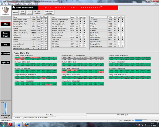
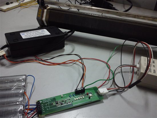
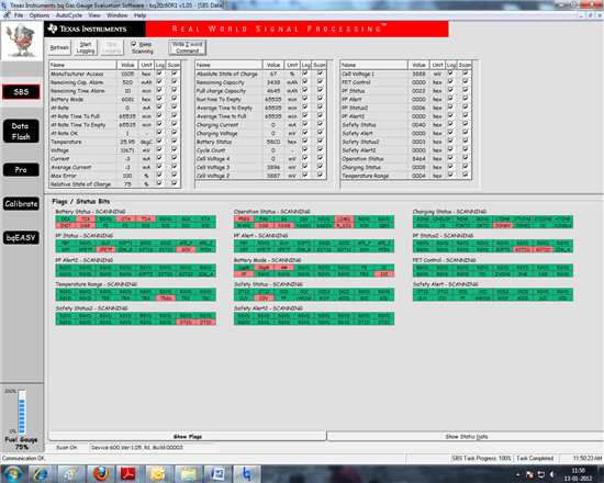
How can I config. the bq20z60evm  for 3s2p(or send me a links/documents that could assist me).

What all thing needs to be changes while configuring  the EVM

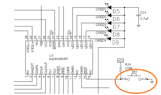
What set up will show the LED indication for full/no Charge.

Sad that no documents are provided with the EVM pack

Thanks

  • Nikhila,

    There are a lot of reference documents provided for our gas gauge devices, so we prefer users review and choose the documents that best fit their needs. This saves a lot of printing and shipping costs as well as reduces waste. The EVM kit should have included instructions as to where to find the bq20z60 website location on www.ti.com.

    Have you downloaded the bqEV software? It is located on the bq20z60 website and provides tools to assist you in configuring the device. The datasheet and TRM provide information on the how to setup the LEDs to display the state of charge for the batteries. 

    Best regards

    Tom 

  • Dear Tom,

    Thanks for the mail. I have all necessary SW/tools.

    But still have a few Questions:

    1. Should I Use the switch when ever i want to see the SOC?How can I avoid triggering the switch and always monitor my SOC.
    2. If I am using bqEASY, do i need to do the caliberation.?
    3. Once I configured the EVM can I redo it again?

    Please find the attached documnt/screen shots describes how I had gone about this.

    Please tell  me if   i am going wrong..

  • Nikhila, 

    Here are some comments to your questions.

    1) I am not sure what switch you are referring to.

    2) Calibration is part of the bqEasy procedure. You will need to calibrate everything except for the external temperature sensor.

    3) Yes, you can change the configuration later. Don't seal the pack until you are finished and this will make it easier for you.

    I made some comments in the document that you sent.

    Regards

    Tom 4505.4375.bqEASY mail 2.pdf

  • Thanks Tom!!!

    1. I meant the display s/w. Display is on only when the interrupt is applied, How can I modify it to get a conti.display of SOC?

    2. what to answer for this? What it exactly mean and Consequences if configured wrogly.

    3.Now While configuring the module I got a message about a flag? where / how to clear this (which) flag?

    thanks for the help

  • Nikhila,

    1. The LEDs will light when the DISP input is held low. You should be able to keep it low and provide a continuous display. This will draw more current from the batteries.

    2. Some applications have non-removable battery packs and this radio button would be selected, if the battery is not removed. The device will ignore the PRES/ input, if you select NO.

    3. You can use the "Write 2 Word Command" button on the SBS screen and write Word1 = 2673 and Word2 = 1712 to SMBus Command 00 to clear the permanent failure.

    Regards

    Tom

  • Dear Tom,

    I almost solved previous problem but facing another issue.

    I connected a battery pack, charger of 13.5V and a load in the concerned places. But Q2,Q3 and Q4 are heating up so much, that i could no longer continue the config(image attached).

    1. Why is it happening?How to solve/ continue my work?

    2. I realised that the cell pack is getting charged(initially was 6V, with in seconds it became 10V, but Mosfets were dam hot), But I am usinga charger with out anyher protection circuitry on my cell pack other than the HPA435. First level and second level protection of BQ29330 is sufficient to protect my pack or do I really need an extra protection circuit

    ( I am using a charger)

    3. Or could you suggest me the best suitable charger and load for the testing , if any ?

  • Tom, I tried writing the flag reset (see figure ) but still getting the ld message that flag  should be reset.WHY?

  • Nikhila, I would check the cell voltages to make sure that one of them is not damaged. The charger also has to be able to provide adequate voltage and current to charge the pack. You may want to start with a good power supply until everyting gets setup properly. If the cell voltages are different, then you may want to pre-charge them to make it easier for the system to start working. Could you sed me a .gg file and .log file to hel analyze the problem? Thanks Tom
  • Nikhila, The screen shot shows that you have a SUV fault. The command cannot clear the fault, if a valid fault is present. You may have to disable the fault until the system gets setup properly. You can do this by setting the timer for the fault to 0. Regards Tom
  • Tom,

    1. Even if I press the switch for a long time the display leds are not bright/ON. In that case if i grounding the DISP\ pin, will it work?

    2. Earlier battery pack had a problem (one cell was damaged.).Now I made a 3s1p package with all cells having 3.4V.Sill the mosfet is getting very hot but abate after a minute and again heats up.IS it normal?

    3."You can do this by setting the timer for the fault to 0", but how to? I am not write in this register (if the reg. Where I am trying is correct.)

    4. How to make the GG file? I am still not able to reach the last steps of BQeasy .

  • Earlier post was not showing this image:-( (this is the reg. where i tried to change the flag ,but not reflecting/ allowing)

  • Nikhila, 

    I am fairly new to using this device, so I will need to try to recreate your experiments. The documentation says that the DISP is H-to-L triggered, so maybe it only stays on momentarily. I will have to confirm whether the LEDs can be held on continuously.

    Faults can be disabled by setting the respective timer values to 0 on the Data Flash screens.

    Best regards

    Tom

  • Dear Tom,

    I an sending you my first set of .gg/log files. Before charging the cell.I will send you another set after charging the cell. I am able to conceive the procedures ...but more to go.

    Now I think ,I don't need a charger module since this module cal do it with enough protection. What do you say?

    4846.GG LOG 321P.zip

    I made some m0ore changes. that will come to you later.

    Please do provide info to display the status conti.ly.

    regards

    Nikhila

  • second set.0410.3s2p secondlog.zip

    how to reset SOV flag?

  • Nikhila,

    I reviewed your .log and .gg files and do not see any entries that would cause the device not to operate. The SOV flag is set in the .log files from the beginning, so it does not offer any insight as to when the fault occurred. You can disable the SOV fault from reporting by setting the SOV time to "0". (see the attached file) You may have to send the PF clear command mentioned in a previous post to clear the fault after setting the SOV time to "0".

    I checked on lighting the LEDs continuously. The LEDs only light for 4 seconds after the the DISP/ input transitions low, then it will turn off. The device offers the option of lighting the LEDs continously during charging, by setting the CHGLED bit in the Operation CFG A register. We do not offer the option to keep them lit during discharge.

    Best regards

    Tom

    SOV time.pdf
  • Tom, I tried Uninstalling the software and reinstalling it, as the older software is not functioning.

    1. Each time after II remove EV2300 hardware from the USB port, I am forced to install the driver software again and again.(Otherwise it is not recognizing.  I triedw with both 32 and 64bit Win7)

    2. When I tried installing the bqeasy, "software is corrupted/ didnn't down load fully " msg is coming.

    3. When I tried with the old file, "device is not compatible, proceed at your own risk" msg is coming.

    4. Many times I noticed , with out charger connected to the slot, gas gauge indication is not 'ON' (even if the hardware is connected to the system). how to solve this?

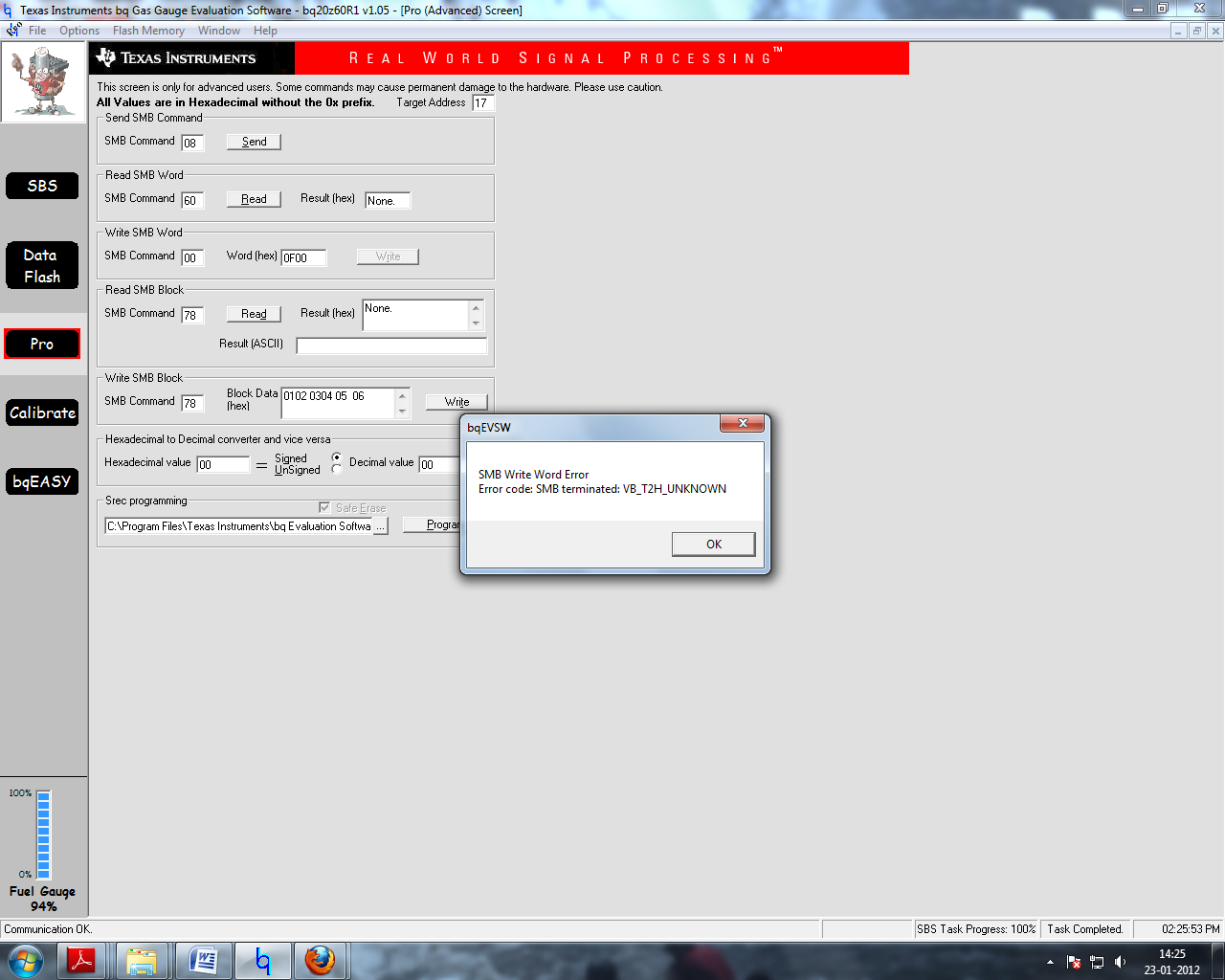
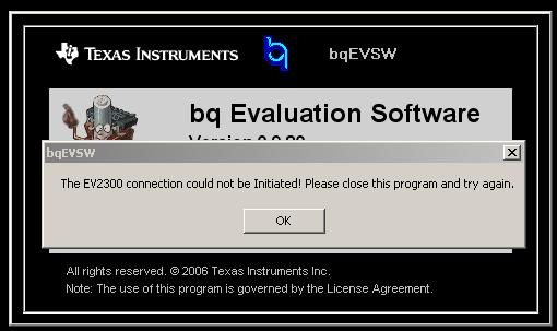
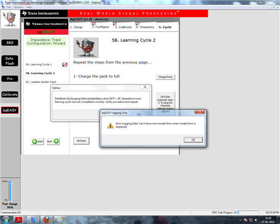
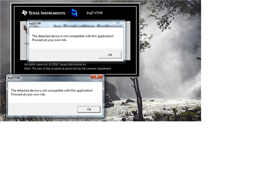
  • How to solve these ??
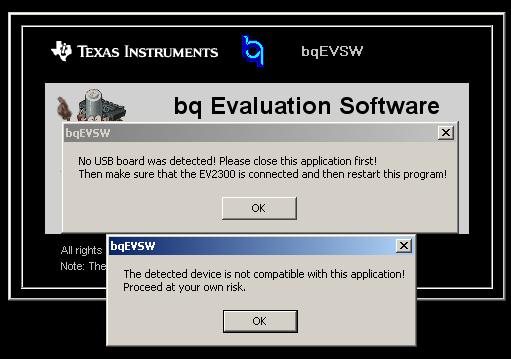
  •  

    Nikhila,

    I have run into two issues when trying to setup comunications.

    The first one indicates that communications with the EV2300 cannot be established. If you get this one, then you may have to go to the Windows System screen and delete the EV2300 and re-install it.


    If you do not get the first one and get this warning, then this indicates that the EV2300 is working properly and BQEVSW does not recognize your EVM. The device could be damage or the the firmware could be corrupted. You can try reloading the firmware. I attached an applications report. I will attach the .senc file in the next message.

    Regards

    Tom


    updating firmware.pdf
  • The the EV2300 warning was missing.

    bq20z60_r1_0105_bld_0003.senc
  • Thanks that is working.

    But two other new problems.

    .

    Why it is coming...after a number of trial...it again started working.

    Why not scanning the PF staus regs?

    Could you give me a proper insight to the cycling process.

    First cycling takes less than a minute but second one almost 2 hrs. Before I finish the second cycle , it is getting cancelled.

    Whta i did is ,I just connected the charger and a load to the module plus the cell and put it in the cycling.

    Am I correct???

    After I make the golden imgae ,How will i send that to the new ICS?

  • Nikhila,

    Some people have problems using bqEasy to run the learning process on a pack. The manual method will probably work better. Are you still using our EVM for the evaluation? The golden file (used to program other devices) should be created on your module, becuase this will allow the device to compensate for the PCB, battery connections, etc. You can create the golden file using our EVM, but the final setup may not be as accurate.

    You can pull a couple of documents from the TI website to help with the learning process. SLUA597, SLUA355B

    The communications problems that you noted may be due to bqEVSW trying to execute a command while scanning is active.

    Manual learning process

    When no close Qmax value is known:

    1. Even though accurate capacity is unknown, set Qmax and design capacity to the cell capacity shown in the data sheet. Do not send IT enable command 0021.

    2. Send SMB command 46, word 0006 to turn on the FETs.

    3. Discharge the pack down to termination voltage at a C/5 rate.

    4. Let it relax for 5 hours or more.

    5. Send the IT enable command (0021). Bits QEN and VOK in Operation Status are set.

    6. Charge pack to full capacity until the taper current is reached and the FC bit is set.

    7. Let it relax for 2 hours. Qmax is learned at this point; this can be verified by MaxError changing to 3% and Update Status to 5%.

    8. Discharge the pack down to terminate voltage at the typical low rate of your application. For laptops, it is usually C/5. The MaxError changes to 1%, and the Update Status changes to 6%.

    9. Repeat steps 4 and 6 to 8 one more time to verify the gas-gauging accuracy.

    Regards

    Tom

  • DEar Tom

    Please let me know why PF status reg. (which contains the cycle info) scanning is in grey(not scanning). -image attached in my last mail.


    .


  • Dear Tom,

    with all the error msgs and troubles, I managed to finish the cycling and did the goldenn image.

    I am attaching the files before and after cycling and also the golden image( though I am not able to read it).

    Two error messages at the end is also included.(I have to repeat it all again for 3s2P pack.)

    Please have a look and comment.

    Plz answer to my previous question.

    One crucial/ simple(?) queston is that Can I connect an adapter instead of a charger to this module? DO this have sufficient cell protection?

    Can it switch between pack and the load?

    5444.final bq.zip?

  • Nikhila,.

    I answered the grey box question in the previous response. The grey box could be a communications problem where the program is trying to read communicate while scanning is enabled. It is better to disable scanning while accessing registers.

    I tried to review your golden image files, but they are corrupted. It looks like something went wrong while extracting the .gg file and the .dfi could not be read. The .gg file has data from what looks like a blank device. You can try reading the .gg file again and send it to me.

    Regards

    Tom

  • Even after disabling 'scanning' ,that box is grey. In this case Do I need to repeat the whole steps again?

    How can I reset the configuration. If I do so, can I skip the cycling?

    gg files attached.

  • Nikhila,

    Does the box always stay gray or does it work some of the time. I have had boxes turn gray intermittently. This is caused by communications problems. It could be any number of things such as conflicts, noise, battery too low, etc. I would not worry about it as long as it only happens intermittently.

    I did not see the .gg file attachment. You may have to rerun the learning cycle, but I will know more after reviewing the .gg file. You would need to reload the .senc file to reset the configuration.

    Regards

    Tom

  • Worrying thing is, it is always grey.

    When I tried to re configure, another write error is coming. Please check the attachment

    How to solve this?

  • Dear Tom

    I would like to describe the steps I followed to configure the module.

    Please point if its wrong.


    1. Install the bqEVSW software and USB drivers for the EV2300 communication box.
    2. Connect resistors and power supply to simulate battery pack.
    3. Kick-start EVM( Connect a charger to pack plus and pack minus).
    4. Run bqEVSW software.
    5. Now, connect real battery cells to the EVM. (Note: connect from lowest voltage 1N to highest in order to avoid damage to the analog front-end IC.)
    6. Go to BQEazy Configure it with correct details. Complete the cycling.
    7. Log the details
  • Nikhila,

    If you are getting gray boxes and this communications error, then you are probably in ROM mode. The screen also shows the 0F00 may have been written to SMB Command 00, which is the command to enter ROM mode. You can press the SMB Command 08 button at the top of the list to exit ROM mode and communications should be restored. The only time that you would need to enter ROM mode is when you want to reload the .senc file to restore the device to new from the factory state.

    You should not have to start out with resistors to "kick start" the device. I would recommend that you start with new, fully charged batteries and connect them to the EVM. Temporarily short 4P to Pack+, connected the EV2300, then start the bqEV software. You should be able to select the Start Scanning box on the SBS screen and the boxes should turn red or green.

    If you are having problems with bqEasy, then I recommend using the manual procedures that I mentioned in an earlier post.

    Good luck ,

    Tom

  • "You can press the SMB Command 08 button at the top of the list to exit ROM mode and communications should be restored"

    I always do that. But this time its not working,instead showing an error message.

    How to come out of this?

  • Your screen shot shows that communication is okay at the bottom left corner. You can try reading SMB 0D to see if it is in ROM mode. The returned value should be less than 64H (100%) if it is in active mode. You can check VCC to verify that it is 2.5V, indicating that the device is working. The only other thing that I would have you try is to reboot the computer and reconnect everything. I have had EV2300 problems that caused communications problems before. Otherwise, you can send the EVM and batteries to me and I will try to repair it and create your files.

  • Tom,

    Now it always shows communication error. 0D value is 0301.

    sending the unit along with battery would be difficult(EXPLOSIVE )

  • Nikhila, The 0301 data means that the device is in ROM mode. Please try reloading the .senc file and then the command to take the device out of ROM mode. If this does not work, then you may have to use a new EVM. Regards Tom
  • When I run BQESW  " not compatible " message is coming....VCC is 2.4V.

    Still,do you think its the problem of EVM?

  • Nikhila,

    It is normal to get that message after you load a senc file. We send it so that you will reinitialize the bqEVSW to make sure that you are running the proper version. Otherwise, you may not access the proper register locations. The bqEVSW should recognize the EVM and start back up without the error message. VCC should be close to 2.5V. Maybe we should have a conference call and WebEx session, so that I can look at a few things on your setup. Please enter your contact information in your biography and I will contact you outside of the forum.

    Regards

    Tom