This thread has been locked.

If you have a related question, please click the "Ask a related question" button in the top right corner. The newly created question will be automatically linked to this question.

UCC28019 Operation Basics

Other Parts Discussed in Thread: UCC28019, UCC28019A

Hello! I am currently designing a PFC circuit using the UCC28019. I havent finished soldering everything into place, but I need to report on some specifics when I get done. These include the switching operation of the IC. I am just wondering which part of the sample circuit governs the ripple voltage? I assume that the gate turns the mosfet switch on (close) when the output voltage (governed by the voltage divider at VSENSE) reaches a certain voltage above the nominal output voltage, and then it turns off (open) when it reaches another threshold below the nominal output voltage. Am I correct in assuming this? If I am, then how are the max and min thresholds adjusted?...

  • The gate is turned on by the internal oscillator, turned off by the fb loop, which has dependency on the Vsense voltage.  I am enclosing the pdf of my MathCAD file that I used for the UCC28019 EVM design in the hopes that it provides you with more detail than you really want to know. If you have MathCAD, I can send you the worksheet itself.  The equations are what's "behind the scenes" of the Excel Design Calculator that is in the UCC28019 product folder.

    Just as an FYI, the UCC28019A has the same pin out as the UCC28019, same design procedure, but the enhanced dynamic response was improved to minimize audible noise during start up and transient response. 

    Mathcad - UCC28019 Design Calculator.pdf
  • Thank you for the file. And the info. =)

    I have another question though. The datasheet says that the UCC28019 has soft-start that limits input current at start up. But the schematic of one application I saw had start up mechanisms that involved inserting a resistor and relay between the rectifier output and boost input. Is it really necessary? Especially for my application which is for a 2KW load.

  • Oh and another thing... I've had a few mosfets explode already, I'm still troubleshooting my circuit, but is there any way to test if the UCC28019 is still operational? Without the whole highvoltage setup. I'd just like to know if i can still use the one i have and make sure that it wasn't destroyed after the first mishap. Thanks!

  • Danel

    The resistor is there for two reasons. The output capacitors of a PFC are usually large and not subject to inrush surge protection when the supply is initially plugged in. If  you look at the schematic that is easy to see. The resistor is there to prevent the charging of the output cap from pulling too much current. If the current surge will damage the diode bridge or result in the input fuse blowing then the resistor and relay can be added.

    During the initial charging of the output capacitor and before the PFC starts the really is open. The realy should be closed before the PFC action starts.

    Regards,

    John


  • Danel,

    Replace the IC. It is not worth your while to try and identify is there is damage. It could be a latent failure.

    From your previous E-mail I gather that you have not got a resistor  in series for start up. This brings up the second reason for having the resistor. During startup without the resistor there is good chance that the output capacitor will resonantly charge resulting in the voltage on the output caps being up to twice the line voltage. If that is the case the first pulse from the PFC can result in the voltage on the drain of the FET going to twice the designed voltage and blowing up the FETs. See the referenced paper http://powerelectronics.com/passive_components_packaging_interconnects/circuit_protection_devices/power_pfc_circuit_halts/.

    Usually designers place a diode from the positive of the rectifier bridge (at the PFC inductor to the cathode of the PFC diode to prevent the resonant action which can result in the output caps going over voltage.

    Regards,

    John

  • One last question. Ms. Lisa mentioned that the UCC28019 and UCC28019A are exactly the same in functionality, etc. But what exactly is the difference between them? Also, why is it that the description (in the website) for UCC28019 says that it's for systems of "100W to >2kW" while the description for the UCC28019A omits the ">" sign, ("100W to 2kW")? Is that just a typo or do they really differ in that limitation?... Thanks!

    By the way, I was able to make it work now, just a minor problem with burnt control circuit components and a major change in inductor construction. Hehe. I'm able to go up to about 1kW now.

  •  

    I'm glad you have the circuit working (after a minor destructive phase...).  The enclosed slide lists the differences between theUCC28019 and the UCC28019A.  Basically the "Enhanced Dynamic Responsive" got scaled back a bit on the A version. PFC loops are, by nature, slow to respond to transients.  The UCC28019 dynamically speeds up the loop response when called into action; sometimes it was determined that it was a bit too enhanced and the circuit would experience hitting OVP for several cycles before everything settled in; this was tuned down in the A version so the result of a fast response to  a transient is the same, it just does it in a kinder, gentler manner.

    As for the > 2kW verses the to 2kW ...the ">" sign really shouldn't have been put in the original UCC28019 data sheet and was in fact consciously omitted in the UCC28019A data sheet. Realistically a controller is just that, it sends control signals to the rest of the circuit.  The power stage is what limits the power.  Theoretically you can use either one of these device for a gigawatt design but realistically, wouldn't you want to have more control features than what any 8-pin controller can offer for something that massive?  The 2kW is an arbitrary limit that we would recommend as a practical application for this device, but neither is limited to this value. 

    UCC28019 vs. UCC28019A.ppt
  • Hello again!

    I've just been able to reach 2.2kW. I tried to see how long it could operate but it didn't last a minute before the mosfets exploded again. I discovered that the diodes failed. If you remember i used 4 RURP8100 in parallel for the boost diode (i didnt know that using diodes in parallel was not a good idea). The peak inductor current reaches almost 15A at maximum load. So now I replaced the 4 diodes with just one RHRP1560. The previous diodes could hold 8A each, whereas this new diode could go as far as 15A. I'm planning to test the new setup just until 13A peak at the inductor. At least until the new 30A diode i ordered arrives.

    But anyway, what's bothering me right now is the noise that the PFC produces at about 1.2kW. It's like a crackle, aside from the 120Hz buzz. Is that normal?...

    Also, i see this behavior in the inductor current (blue line):

    It happens at the "shoulders", the place where the line current slope starts to decrease as it reaches the peak. Is the IC supposed to behave like that at those points? At other points, the gate voltage pulse is more or less smooth or at least a pattern is evident. Thanks!

  • Danel,

    It looks like you are hitting your current limit and that is resulting in the problem you are seeing. Try reducing the current sense resistor by 50% and see if the performance improves.

    Once you have any other issues solved then you can go back and fine tune the the current limit point.

    Regards,

    John

  • I have a question regarding the peak current limit functionality. The datasheet says it (the PCL) activates when the voltage at Isense reaches about -1.08V. But when i look at my Isense, it doesn't beyond -600mV and yet you're suggesting that the PCL is being activated already?

    At 600W, I'm not seeing any PCL activation since the pulse dutycycles are as expected, and the PFC is silent. At 900W, I'm starting to hear a slight buzz, and that's when the pulse skipping happens. But when i look at my inductor current, it doesnt go beyond 12A. Right now my Rsense is 0.033 ohms. I assume that the peak current should be about 30A? Since -1.08/0.033 = 32.72A. Is that the correct computation?... I'm kind of confused right now...

  • Danel,

    Send a copy of your schematic with values.

    Get high resolution images of the voltage on pin 3 using pin 1 as the scope ground reference. the images needed are one complete cycle of the unit having the problem then a zoomed in image of the waveform at the initiation of the problem.

    Since we are looking for noise pick up it is important to use short leads on the scope probe (tip and barrel techniques if possible) and remove bandwidth limiting on the scope.

    Regards,

    John

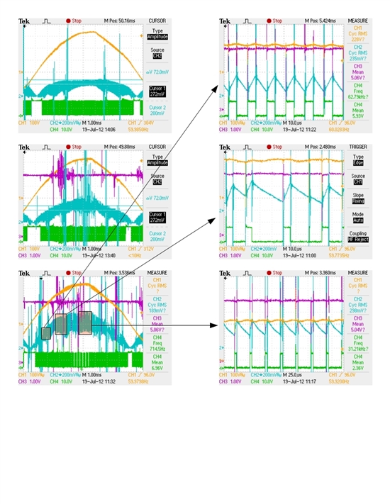
  • Ok, so this is what happens. The column on the left is the zoomed out waveforms of the Isense pin (pin 3, light blue, inverted) with respect to pin 1 (GND), gate pulse (pin 8, green), and Vsense (pin 6, purple). The top is for 600W, middle is 750W, and bottom is 900W. As you can see from the 750W, the middle part of the Isense waveform is starting to become a little distorted compared to the rest of the waveform. If you zoom in on that, you will see intermittent pulse skipping in the gate pulse. Now, when I get to 900W, the distortion becomes wider. I've zoomed in on particular points in the Isense waveform, as indicated by the arrows. At the beginning of the waveform, it's regular, with the gate pulse frequency at around 63kHz. Then when it gets near the top, some intermittent pulse skipping occurs as shown. At the peak of the waveform, I was surprised to discover that the gate pulse frequency has been halved! It's now around 31.21kHz. It means that the IC skips every other pulse. I don't know why it's happening. I'm posting the schematic after this post, but you will see there that I placed twelve 0.33ohm resistors in parallel to reach the recommended Rsense value which is around 0.025. But right now, the number of 0.33ohm resistors is 10. That means an Rsense value of 0.033ohms, making the peak current limit 1.08/0.033 = 32.73. What's confusing is that the isense doesn't even reach 1.08 and yet some pulses are being cancelled...

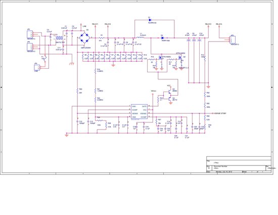
  • This is my schematic:

    Again, my specs are:

    Output power: 2200W

    Output voltage: 385V

  • Danel,

    The reported power levels and the power levels from the waveforms do not agree. Looking at the top left waveform the peak of the current sense voltage is approximately 240 mV. The next one down is about 272 mV and the lowest is about 300 mV. The current sense resistor from the schematic is (0.25 ohms/12 resistors).

    Taking the RMS value of these voltages and dividing that by the effective resistance we get 8.1 amps RMS, 9.2 amps RMS and 10.2 amps RMS. Multiplying these currents by the RMS value of the input voltage (340 V peak = 230 V RMS) we get power levels of 1.87 kW, 2.12 kW, and 2.34 kW. Or 3.1, 2.8, 2.6 respectively times the reported levels.

    In the words in the test the 0.25 ohm resistors are 0.33 ohms. which gives an effective resistance of 0.028 ohms and results in a power level of 2.36, 2.145, and 1.97 times the level he is reporting. He should correct his schematic before sending it out for analysis in the future.

    If either value for the Rsense resistor is correct then he is definitely going into normal current limit. This isn't a problem except there is a discrepancy between what the customer thinks he is doing and what the scope says he is doing.  That should be resolved. Does he actually have all 12 current sense resistors properly connected? 

    In the high power waveform the controller is in fct skipping pulses.  This is caused by the icomp going above 7 volts and not coming down in time for the next pulse so the next pulse is missed (correct behavior). This is caused by subharmonic oscillation on the ICOMP signal resulting from the overcurrent condition resulting from the overly large ripple current compared to the average. His PFC inductor should be bigger. To overcome this he may have to increase the ICOMP capacitor.

    Remove the probes from Vsense and Gate. You can tell when the gate is high by monitoring the current.

    Connect these probes to Vcomp and ICOMP. I expect that ICOMP will have significant ripple and be exceeding 7 volts because of it.

    Things he can try after he resolves the difference in the power levels discussed above.

    Do these separately:

     1st try doubling the cap in ICOMP and see what happens.

      2sd try increasing the PFC inductor

    Regards,

    John


  • Hello!

    Thanks for insights! And yes, I'm really sorry about the schematic. It's supposed to be twelve 0.33ohm resistors in parallel. I forgot to change the values.

    Also, you are correct about the Icomp exceeding 7 volts, but not because of voltage ripple, but because the crest of the waveform is very near 7 volts. I guess there's something wrong with that?... When the output is at 600W, the peak Icomp voltage is already at 6 volts. When it gets near 1kW, the top of the Icomp voltage is already touching 7 volts. What could be done to decrease the gain of Icomp? I mean, it supposed to be the average of the Isense voltage with gain, right?...

  • Danel,

    The current limit kicks in a 7 volts. There is nothing wrong with that as long as your power levels under normal operation at minimum line maximum load keep that voltage below 7 volts.

    The filtering of this pin is intended to remove to a large extent the cycle to cycle ramp voltage caused by the switching voltage across the PFC inductor which should leave the sine wave you see plus some ripple.

    The crest of the waveform  should reflect the sine wave of current into the converter. If it is at or near 6 volts at 600 watts you will be starting to limit the peak if you go much higher. Has the difference in the reported power levels and the information gained from the waveforms been resolved. Is it really 600 watts or is it really 1800 watts as discussed in the previous E-mail.

    The internal gain of the IC can not be changed. You can increase the Ccomp cap to reduce ripple at the expense of having more phase shift and response to transients. You can decrease Rsense to give you higher power on the output. And you can increase the PFC inductor to reduce teh pulse  by pulse current ripple.

    Thefirst hting you have to do is resolve the discrepance in the reported power against the apparent power from the scope measurements.

    Regards,

    John


  • Ok, I just connected a probe to the Isense pin and measured the current going through the sense resistors and divided the Isense voltage measurement by the corresponding current. I got an average of about 0.05 ohms which is double the supposed 0.025 ohms. Is that, more or less, an accurate representation of the resistance seen by the Isense pin? Cause if it is, then that explains why the Icomp voltage goes up to 6 volts at around 600W. Would it be correct to say that in order to fix this, I need to add more resistors (in parallel) until I get the desired 0.025 ohms seen by the Isense pin? Thanks.

  • I've got a very similar problem to Daniel.

    My application is a 200W PFC circuit. 156V to 264V. 208W max output. Vht 390V. HTcap = 168uF. Lpfc=1.6mH

    I used the design tool spreadsheet and applied the values suggested. Rshunt = 0.22R, Rsense = 220R, C (isense)= 1.15nF, C (Icomp) = 780pF.

    The spreadsheet produces a V comp of 3.48V and that's what I see. At 200W, I see an Icomp peaking through 6V and I see missing and severely shortened gate drive pulses, exactly as Daniel reports. the thing is, the problem is worse at higher input voltages when the current sense signal is a lower amplitude, and it all but disappears at 198V.

    I've tried everything: extra filtering on I sense, more capacitance on Icomp, slowing the gate drive, deriving the aux from a bench supply, re-routing the power tracks, changing the IC.

    I've come to the conclusion that the problem is due to the fact that Icomp actually is used as the OFF time pulse width modulator reference. The amplitude of Icomp is determined by the need to have Doff=Vin/Vout, so it's almost load insensitive, the feedback action operates to keep this signal looking much the same whatever the load. What does happen is that the amount of ripple on Icomp varies and if it ripples up past the point where Doff = 100% then you miss a pulse. Once that happens, there is an incestuous positive feedback and it just bursts into oscillation. It becomes better at light load because peak Icomp level is lowered and although the Isense signal is higher, feedback operates to keep Vcomp away from the 100% level.

    As I see it, the solution would be to use a higher Vht value and a higher value inductor, neither of which is possible in this case.

    Comments? Suggestions?

    help!

  • Carole,

    Please provide the following waveforms during a cycle where the fault occurs: Icomp, Isense, Vsense, and Vcomp on one picture. Under identical conditions provide a second shot of Icomp, VCC, gate, and Vout.

    Please also provide a complete schematic with values.

    Regards,

    John


  • OK, will do.

    Only have a 2 channel scope, but will give you the shots required.

  • 7002.Extract from A model results.pdf

    Attached are some screen shots already taken.

    I comp reference is -4 divisions. problem occurs at  Icomp peaking through 7V

    6431.PFC control.pdf

    FET is STF10NM60, R shunt 0.22R, Cout 168uF, Lpfc 1.63mH

    More later.

  • Carol,

    Please provide the output voltage waveform, Vins, and the Vcomp waveforms corresponding to the conditions already provided. In addition in figure 5.5.1.6.1.6.1 and 5.1.6.2 can you identify the ground reference and the scaling so we do not misinterpret the information.  Remember that if the output ripple voltage is too large it will trigger the accelerated dynamic response.  

    The design of the IC was done around the use of a PFC inductor that would limit the ripple current at minimum line to be approximately 20% of the peak line current at minimum input line voltage.

    Your design seems to be pushing 50%. Please try a PFC inductor with a significantly higher inductance and verify the improved performance. 

    Regards,

    John

  • Hi John,

    Ooerrr, the Figure numbering went a bit awry there.

    In all but 5.1.6.3 the scale for blue is 1V/ div and the reference is -4 divisions.

    In 5.1.6.3. the scale is 0.1V/div and the reference is +3 divisions. The current shunt is 0.22 ohm.

    I've made a lot of progress today.

    I tried tripling the inductor without any apparent improvement. So I went back to 1.63mH. There's no chance of fitting a bigger inductor in there anyway, so I needed a solution that doesn't involve a drastic change in value.

    I then removed all of the noise filtering additions I had made. I observed that by reducing the value of the current shunt, the peak value of Icomp was reduced, so I kept going until at all conditions of line and load the crest doesn't pass through 7V. The magic value was 0.192 ohm (0.22 // 1.5)

    I then added capacitance to Icomp. The spreadsheet suggests 780pF so I added another 2n2 in the end. The input THD fell from 6.68% to 5.79% by doing this which surprised me. I would have thought it would have made it worse, but there you go.

    The unit still fizzes quite a bit under extreme line transients from 165V to 264V at full load, but so far I've not killed anything and it settles down to a nice sine wave in the end, the output not deviating much at all.

    Questions: Will adding capacitance to Icomp contribute significantly to the "fizzing" during line transients? Do I need to have a reserve of input power available by reducing Rshunt further to cope with load transients without audible effects?

    The output cap is 168uF (4x47uF) so the output ripple is really quite low at 210W, 390V

    Thanks for your help.

  • Carole,

    If Icomp goes above 7 volts you start having troubles. The Icomp in your scope shots shows this is occurring. Increasing the value of the Icomp capacitor will impact the response of the circuit.

    Can you send scope shots of the output voltage? How many volts ripple is on the output what happens during the time the Icomp is above or approaching 7 volts? Send pictures.

    John 

  • John,

    I have a minor problem left, it's about the Isense voltage. I'm to try to make it really clear, I'm sorry if it's going to sound confusing...

    When I measure the voltage across Rsense, and divide it by the measured current through Rsense, I get around 0.026, which is the resistance close to what I'm expecting. But when I measure the Isense pin voltage, it's much higher than the one across the Rsense voltage. I'm guessing something's happening between the Isense pin and the Rsense node. The effect of this is, the Icomp voltage peak reaches 7V even before I get to 2kW. Right now I'm at 1.3kW, but Icomp peak voltage is almost at 7V.

    So my question is, in order to override the discrepancy between the voltage across Rsense and the voltage seen by the Isense pin, is it ok if I add more resistors across Rsense to decrease the resistance value until the Icomp voltage only reaches 7V when the output reaches 2kW? Cause I noticed that Icomp peak voltage decreases whenever I decrease Rsense.

    [By the way, changing the Icomp capacitor doesn't do much, the problem is not with the ripple but with the average current. Adding more resistors to Rsense (reducing the resistance) helped me get past 600W without pulse-skipping.]

  • hi John,

    I turned off the equipment yesterday, came back in today and, without having changed anything, the behaviour is different. Now, I can't provoke the previously seen oscillation within the load range. The attached document shows the Vht ripple at ~10V peak to peah with a DC level of 395V. Icomp just pops up through 7V at full load, 230V input, but does not trigger a protection function. At 165V 207W you can see that the overcurrent function is active, flattening the waveform.

    The fact that it's variable day to day, presumably because of temperature, leads me to think that i should be further away from this operating point. my plan is to:-

    Retain the spreadsheet compensation at Icomp of 780pF (680 +100). Adding extra capacitance produced a marginal improvement in THD and isn't worth the risk of additional transient problems.

    Reduce Rshunt to keep I comp below 7V under all conditions of line and load within the range.

    Move on.

    Thanks for your inputs.

    0284.screen shots for Ti.doc