


TI Team,
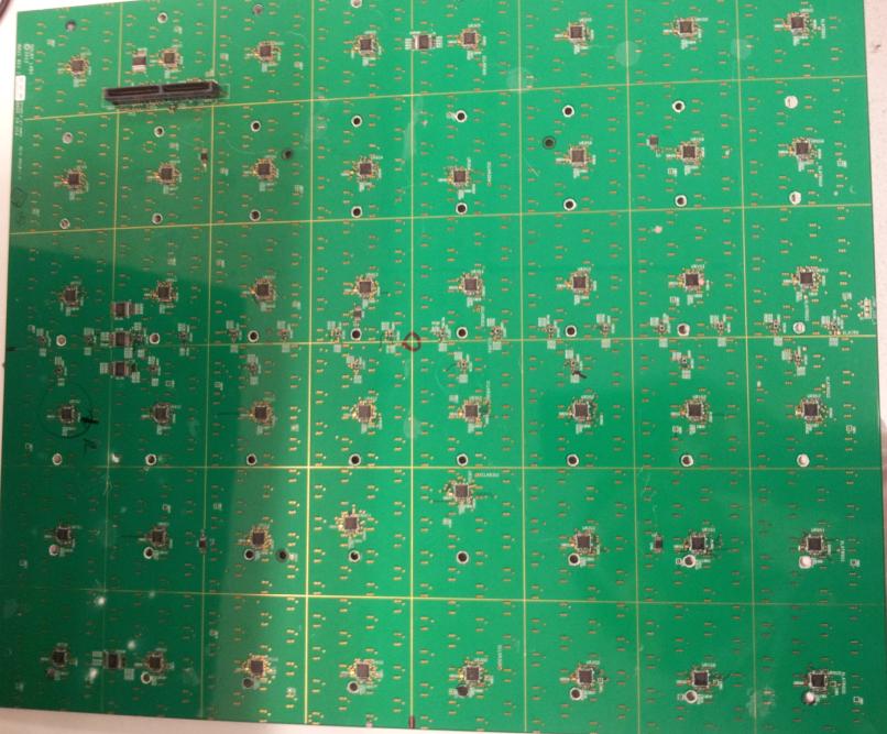
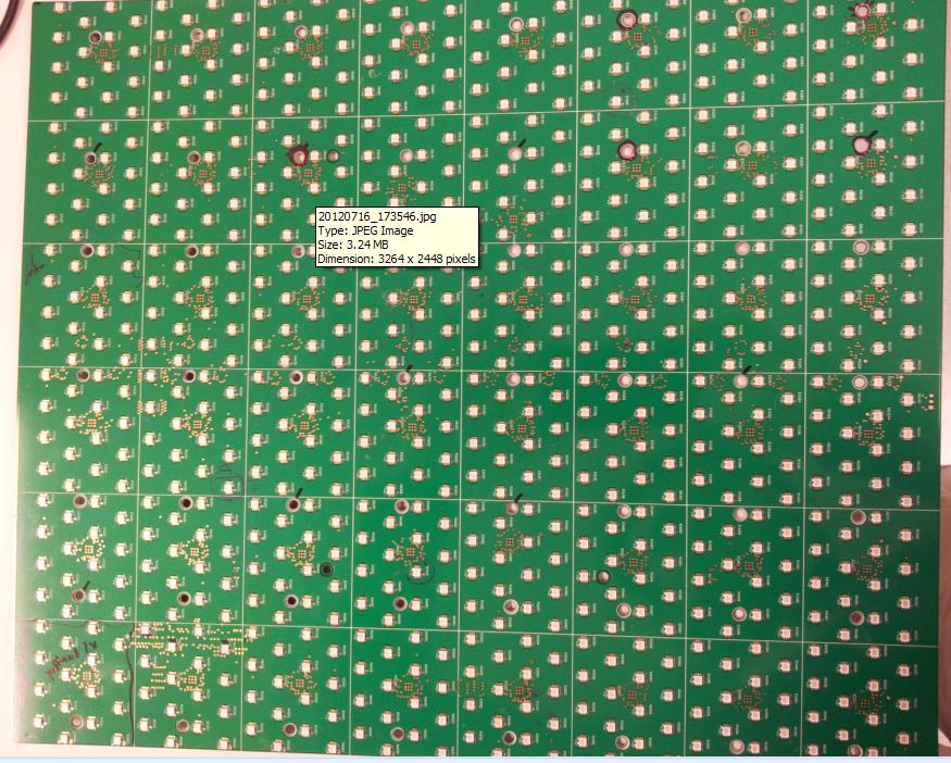
I'm using the TLC5941 in a professional high end video system. I have the TLC5941 configured to drive a several rows of OSRAM LEDS. I've attached two pictures that show the layout of my board, The front side is a matrix of LEDS while the backside is the corresponding matrix of TLC5941 drivers.
Setup
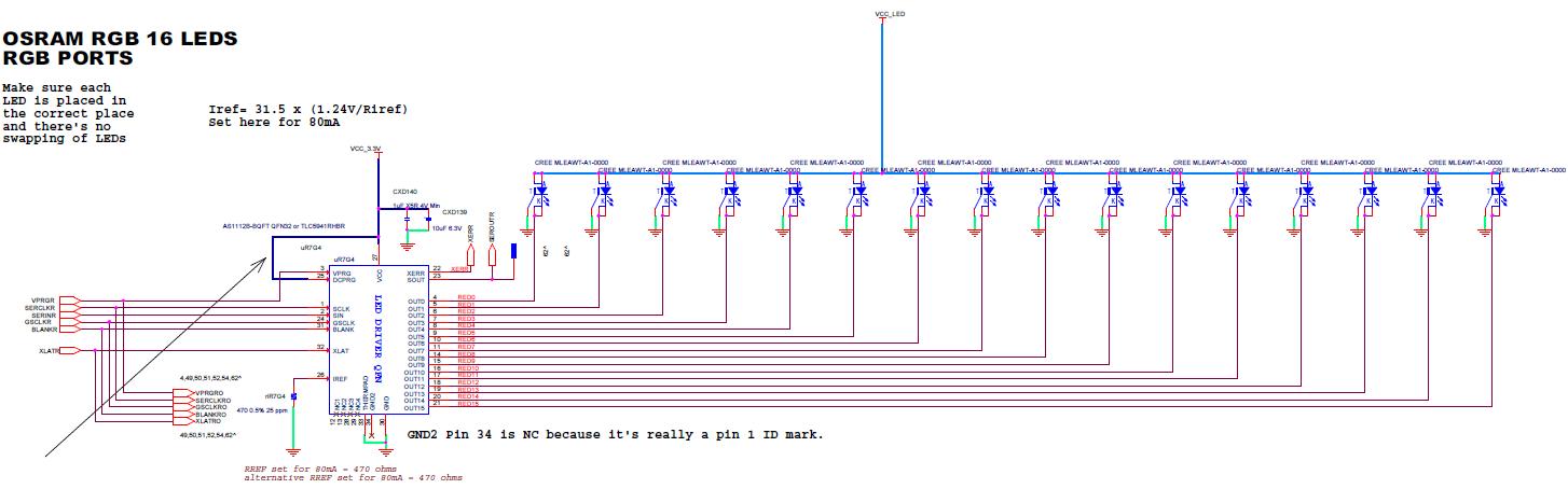
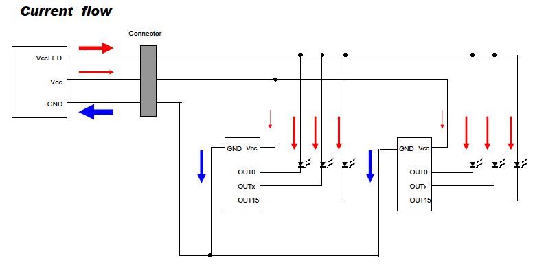
In total, I have 32 rows of 24 LEDS per row. The array is configured in an 8 x 6 pattern where each square contains 16 LEDS. I use 3 drivers for every 2 rows of LEDS for a total of 48 drivers on the backside of the board. (see attached picture of setup). This driver/LED board receives power and control signals from an external board, which includes 3.3V to power the driver and 4.5V to power the LED banks. (see attached schematic screenshot). This external board receives 12V from a system power rail and uses two on board DC/DC regulators to generate the 3.3V and 4.5V. All 3.3V supplies contain reservoir and decoupling capacitor of 100uF and 1uF respectively. The LED supply of 4.5V does not have any reservoir capacitance. The control signals emanate from a programmable gate array, which provides the SERCLKIN, GSCLKIN, XLATIN, SERINR, BLANKR, SERINR, PRGR signals to the driver.
The LED/driver board is a 6 layer board with 4.5V plane being the top, followed by a signal plane, then ground. The ground layer is followed by a 3.3V layer, then another signal layer followed by ground.
Main Problem
When the led/driver board is powered on, the controller begin sending the data to each driver, the LEDs light up. However, if during the test routine we shut down or power down the system, various outputs of the TLC5941 appear to be shorted to ground. The same issues appears when the DOC values are changed thus forcing the reprogram of the part. Upon further investigation we find that the devices showing this failure have very low on resistance to ground somewhere in the neighborhood of a few hundred ohms. When we replace the bad part with a new TLC5941, the system works until we initiate a power down or reprogramming cycle. The failure in this case is on a different driver, so we know the problem is random. In addition, we see that the failure of the device occurs with only 1 of the 16 outputs of the driver.
To summarize our findings:
- Each board has 48 parts, and maybe 1 output on about 10 parts exhibit this phenomenon. Occasionally 2 outputs on the same part will fail.
- After short is detected, when we replace the part, things work until our testing sequence is repeated, i.e. power off or DOC programming.
- We know the failures are not LED based, therefore the LEDs do not need to be replaced.
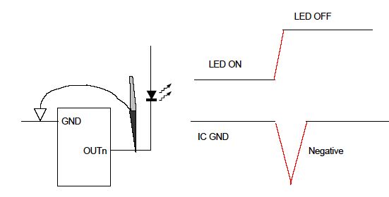
- After a driver goes bad, we apply VCCLED all the bad output LEDs. They immediately turn on (because the OUTx pines are low impedance to ground), indicating the output is stuck turned on.
- On some OUTx pins, we sometimes see a dim flickering and we can't turn LED off or control them.
Next Steps
We have a few questions regarding our setup as well as with the way the TLC5941 functions. Our schematics have been reviewed by local FAE support. Their recommendation was to add bulk capacitance on the 4.5V rail that power the LEDs. However, we still would appreciate answers to the questions below:
- Do we need follow a particular power up sequence between the 3.3V and the 4.5V?
- Would DOC reprogramming cause the drivers to weaken and fail over time?
- What would cause the driver output to fail?
- Based on our layout, are there any recommendations from the factory?

