This thread has been locked.

If you have a related question, please click the "Ask a related question" button in the top right corner. The newly created question will be automatically linked to this question.

LMZ14203H maximum output capacitance?

Other Parts Discussed in Thread: LMZ14203H, LMZ14201H, LMZ14203

Hi,

My customer uses LMZ14203H in several designs.  Vin = 20 to 24V, Iout=2A, Vout is 3, 5, 12 or 18V.  The data sheet does not mention a maximum allowable output capacitance, but Webench predicts instability when output capacitance is increased to around 300uF.

Is there an instability danger if the extra capacitance is separated from the LMZ's output by some PCB inductance? What is a reasonable PCB trace width/length (or inductance value) to isolate the capacitance?

Thanks,

Rick

  • I've used the LMZ14201H with 330uF on the output of:
    Vin: 36VDC
    Vout: 11VDC
    Iout: 0.8A

    without any problems. 

  • Remember there is a difference in which one you use: 

    LMZ14203H is for output voltages above 6V and the LMZ14203 is below 6V.

  • Hello Rick, 

    I happened to have an LMZ14203H eval board handy.

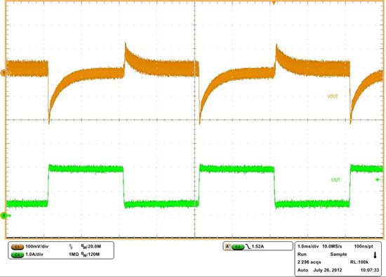
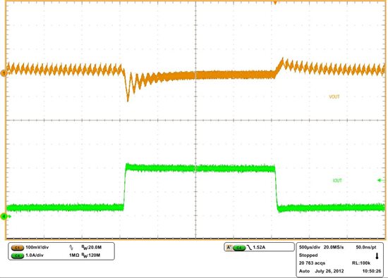
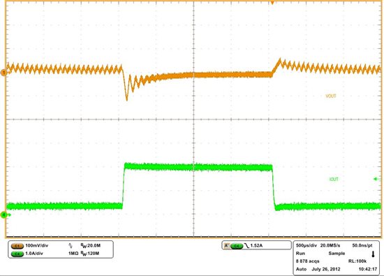
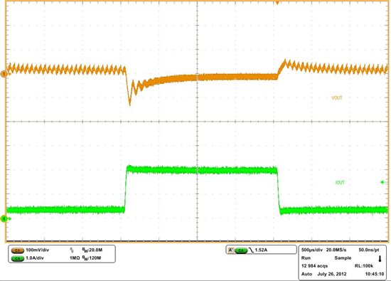
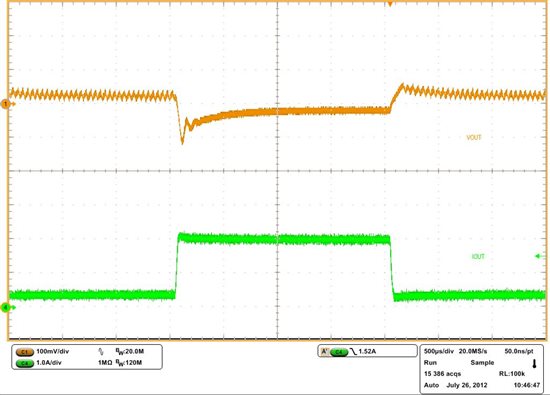
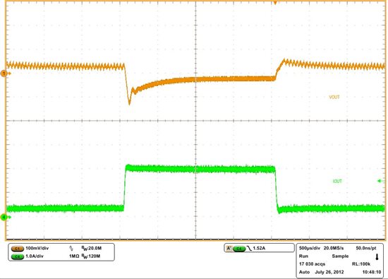
    I tried adding excessive capacitance (additional 470uF) on the output of the standard board (set for 12V output with default 47uF Cout). In steady state the part operates normally. I observed some oscillation during load transients but the output voltage is still well regulated. As the distance of the big capacitor from the 47uF cap increased, the output voltage oscillation was reduced. I also used 10nF Cff capacitor which seemed to work better (less oscillation) with the large output cap compared to the default 22nF. I am attaching several scope shots below:

    Board setup photo:

    The blue marks on the Vout extension board are 1cm apart.

    Load transient with the default 47uF output cap:

    Load transient with the 470uF soldered directly to the 47uF cap:

    Load transient with the 470uF soldered 1cm away from the 47uF cap:

    Load transient with the 470uF soldered 3cm away from the 47uF cap:

    Load transient with the 470uF soldered 8cm away from the 47uF cap:

    Load transient with the 470uF soldered 10cm away from the 47uF cap:

    The input voltage was 24V in all tests. 

    I have not tried other output voltages, but I think it is fair to say that you may see such oscillations during load transient with excessive capacitance. Your case may be better because you don't have as much cap. What is the reason for the excessive capacitance you are considering?

    One question is the %ripple your load can tolerate and the worst case expected transient currents on each of your output rails.

    Regards, 

    Denislav

  • Denislav,

    Thanks for the experimental results.  The question came from the reliability engineer, who noticed the large amounts of capacitance design engineers have placed on the output of the regulator in several boards of a design that is about to release.  I'm not sure of the reason, but suspect that it was done out of habit.  He needs to know if he needs to push for a re-design, since this is a very critical piece of equipment.

    I found this app note that discusses the subject, and generally matches your results, although it is not quantitative.  Are those copper bus bars in the picture?  What are the dimensions? (trying to get an idea of the inductance per cm).

    http://www.ti.com/lit/an/snva166/snva166.pdf

    Rick

  • Hi Rick,

    These were scrap pieces of 2-layer FR4 copper clad boards. Only one layer is actually connected. In terms of copper thickness, I believe they are 1oz copper weight so 35um copper thickness. The strips are ~1.4cm wide.

    Regards, 

    Denislav