- Ask a related questionWhat is a related question?A related question is a question created from another question. When the related question is created, it will be automatically linked to the original question.
Teachers Gentlemen:
National Semiconductor
It is to my liking yet greet cordially ask a small contribution concerning the integrated circuit manual:
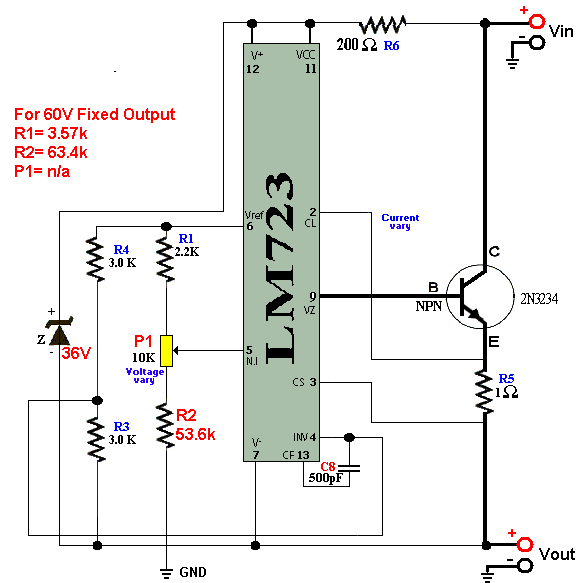
LM723 / LM723C Voltage Regulator
Figure No. 7 manual like this, floating positive regulator, the same according to the manual, some resistance is achieved by changing the voltage requirement of the user, in this case mine is 60V-10 A.
I followed all the procedures manual for a regulated 60 V - 10 A
Achievement of which is the drive to get the current regulation. Plot overview:
- As for the PIN CL No. 2 and No. 3 CS PIN as serious connection and to that point.
- Deputy graphic source 60V - 10 A
- Transformer to use 60 V - 10 A
It agrádese Daniel.