


Hello,
I designed a single stage PFC LED-driver with a UCC28811. I found that the input current has jumps around the zero crossing. I zoomed in on this in the below image.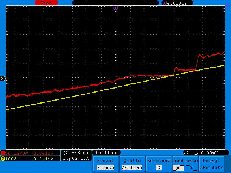
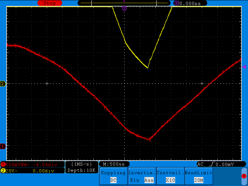
I found that these jumps are caused by the fact that the controller shuts down during appr 500us around each zero crossing. The below image shows the buffer voltage versus the MOSFET gate voltage. As the controller shuts down the buffer is never completely drained to 0V. Because of that there is a current jump when the line voltage gets higher than the buffer voltage and the buffer starts charging again. Then at 900uS there is a second current jump when the controller resumes operation.

I have also seen this behaviour at other UC28811 designs, but with this design it is much longer. Also here I see that the buffer voltage remains at appr 20V for 500uS, whereas in other designs it starts increasing directly after that (see image below)
I am now trying to find out what is different in this design and if there is a way to improve this behaviour. In the other design I can see that around the zero-crossing the FET on-time is very short (see image below).
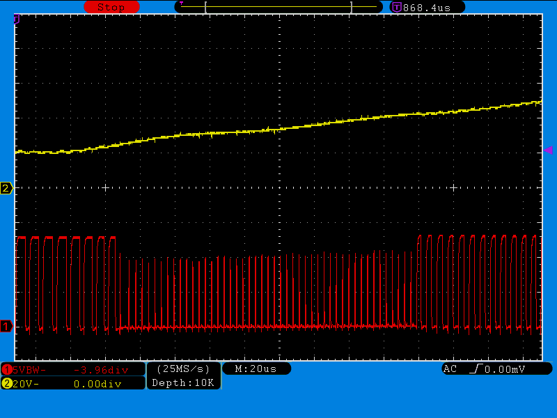
I am not sure why this is. It should have a pretty fixed on-time.
My guess is that in my design the on-time gets so short that the pulses actually disappear. What I don't know is why. As you can see in the images there is a sudden drop in pulse duration around the zero crossings.
Does anybody know why this happens and if there is something I can do about this?
