This thread has been locked.

If you have a related question, please click the "Ask a related question" button in the top right corner. The newly created question will be automatically linked to this question.

TPS53219 Load Regulation: How to Improve

TI Team,

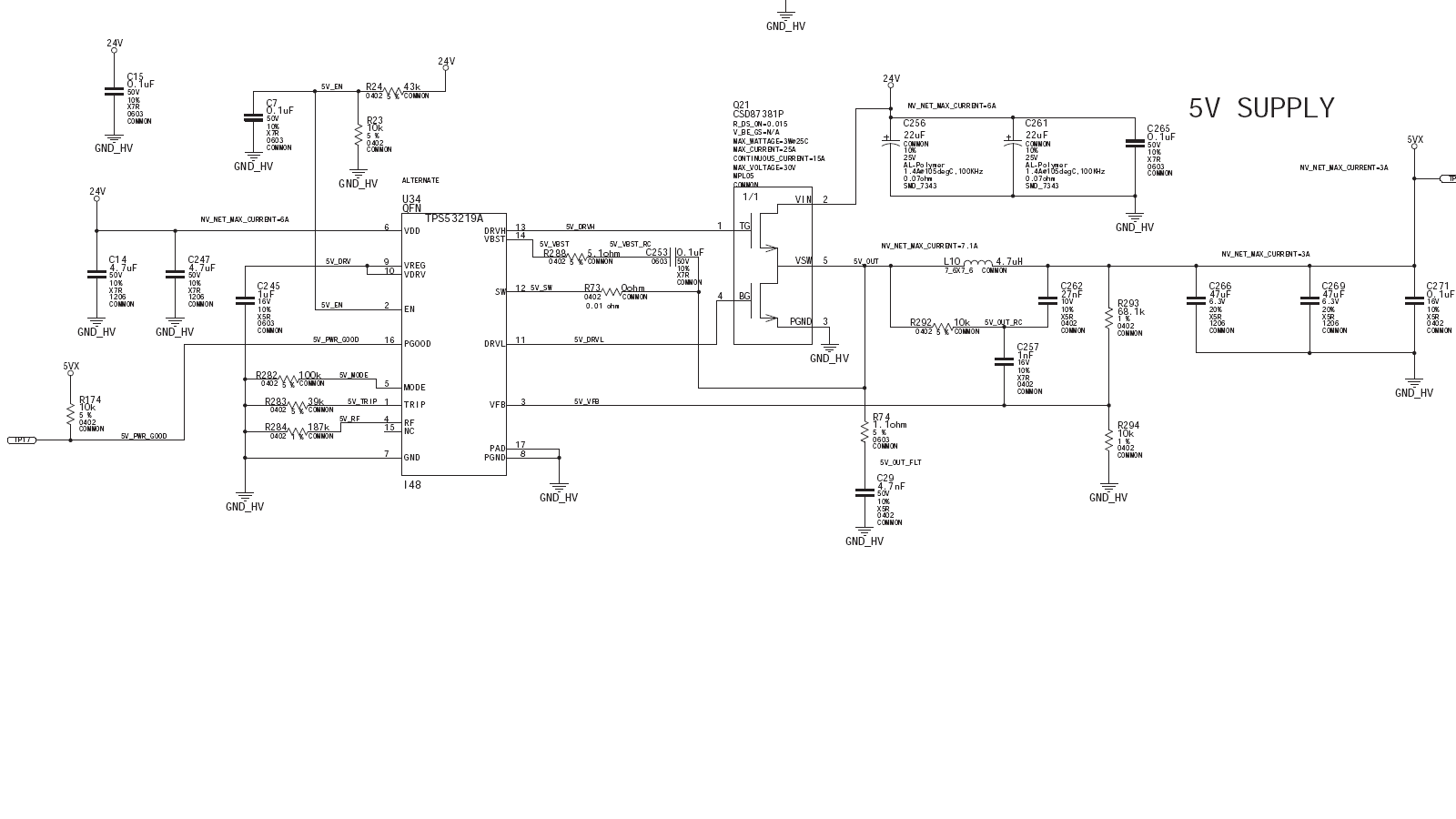
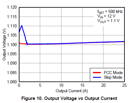
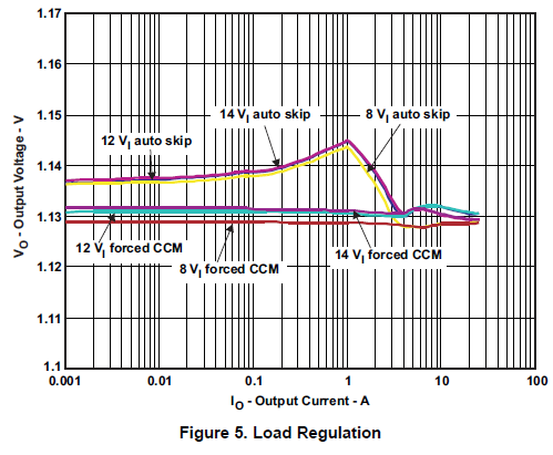
I'm using the circuit configured below (see attached diagram) to regulate a 24V input down to 5V at roughly 6A. I'd like to improve my load regulation particularly at light loads. For example, at no load I measure 4.8V, while at light loads I measure 5.1V, and at high loads 5V. I'm concerned that my data does not agree with is published in the datasheet at 12Vin and 1.1V output. You would think it would be similar at light loads even for a 24V input. Anyway, here is what I'm thinking of trying:

  • Increasing the values of C262 to 100nF (10nF to 200nF) acceptable
  • Margin the supply closer to 4.9V
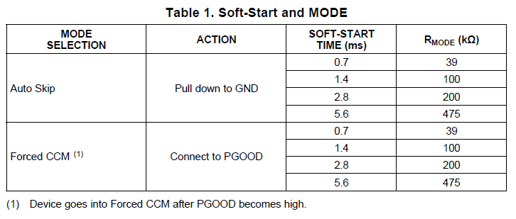
  • For the converter into CCM by connecting R282 to PGOOD
What do you recommend?
-David
  • Hello David, I have escalated this post for you. I apologize for the delay.

  • Hi David,

    Please contact Vincent Su (vincent_su@ti.com) directly. He is supporting this part now.

    Thanks,

    Nancy

  • There will be some variation in the load regulation when the Power-Save mode is enabled.
    Figure 10 in the datasheet shows the trend.


    The EVM users guide also shows the effect in more detail in Figure 5 page 9.:

    YES, FCCM forced continuous conduction mode, will keep the regulation tighter at light loads.
    Connecting MODE to PGOOD will achieve this.

    Table 1 shows the soft start effects of different Rmode values.


    This graph from the EVM also shows the effect of going from Power Save mode to Continuous Conduction mode.
    There is more ripple in Power Save.
    If you are using a DVM to measure the VOUT, it may not give true results due to the AC content of the ripple.
    The output should be looked at with a scope.