This thread has been locked.

If you have a related question, please click the "Ask a related question" button in the top right corner. The newly created question will be automatically linked to this question.

LM27341 switching problems

Other Parts Discussed in Thread: LM27341, LM27342

I have a new design with LM27341 converter.

Vin=15-16V

Vout=12V

Cin=10uF+1uF

Cout=10uF+22uF+22uF

L=3.9uH

Prototypes work well, the regulated output was 12V, but the switching signal was not the best. With Vin=16V the signal has some falling peaks during the Ton time:


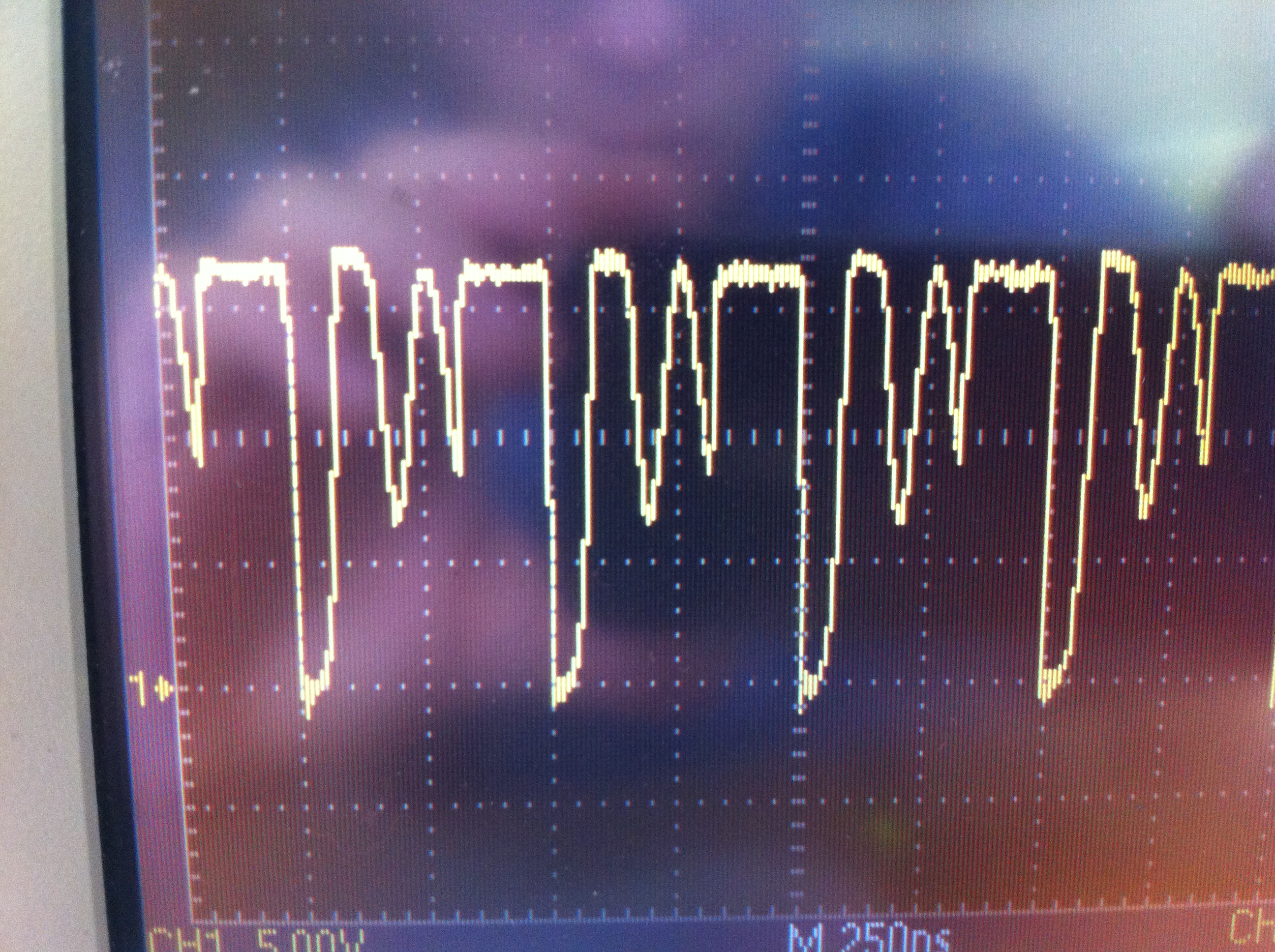
If i decrease Vin to 15V, one of the peaks disappears:

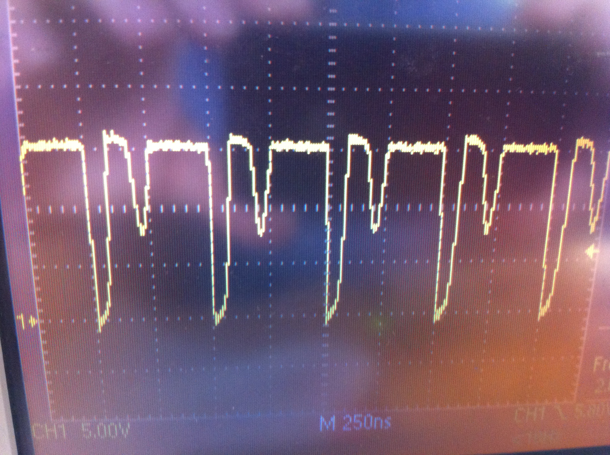
It is not until 14.2V, when both peaks desappears.

If I increase the inductance to 10uH, the switching was OK.

Now, we have 30 units preserie and the LM27341 is not switching. We have 4.23 in the output. With the oscilloscope before the inductor, we see a 4.23V continuous signal. The same signal at the boost pin. If we increase the inductante to 10uH, the switching is like the first one, with some falling peaks.

We think the matter is with the minimum load current. This situation occurs when the load current is about 30mA. When the load current increases to 200mA the peaks desappear as well.

For high voltage output a minimum load current is required as it is shown in the datasheet.

How can I calc that min current?

Hope you can help me.

Best Regards,

Iker.

  • Iker,

    To answer your question about the switch node waveform, I think the falling peaks are the result of Discontinuous Conduction Mode (DCM) operation at light load. The LM27342 is an asynchronous buck regulator. The diode cannot conduct negative current. When DC current < (1/2) inductor current peak to peak, the regulator will operate in DCM.

    The falling peak all the way down to ground is when the diode conducting. The wider positive pulse before that is when the integrated switch conducting. After the falling peak to ground is when both switch and diode are off. The output voltage have a few cycles of ringing, which is a nornal part of DCM operation, until the intergrated SW is turned on again by the LM27342.

    When larger inductor is used, or lower Vin voltage, the inductor current peak to peak value will be reduced. The LM27342 could exit DCM operation and operates in CCM (continuous condution mode), where both switch and diode off state is not existing anymore, thus no Vout ringing anymore. Same with higher DC load current, the LM27342 will operate in CCM and the switch node will be clean rectangular pulses.

    For the minimum load needed to charge the boost cap, I need to find out and get back to you. Could you try a higher load and see weather the part will turn on with higher load?

    regards,

    Yang