This thread has been locked.

If you have a related question, please click the "Ask a related question" button in the top right corner. The newly created question will be automatically linked to this question.

LMR 62014

Hi

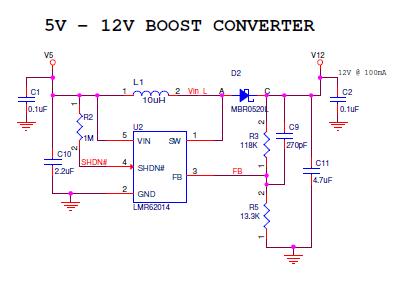
I am using LMR62014 Boost regulator for 5v to 12v @100mA generation.


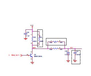
12v boost regulator output converted to 10v and 5v using PWM, using an RC filter followed by this generated voltages.

I faced some issues with this circuit.

  1. When I limited 5V input current below 200mA that time input voltage loaded. I can solve this problem when the input current to the regulator limited to 500mA. Both case there is no load connected. But after some continuous working that regulator failed. Now we lost two more regulators so please check this circuit and let us if we are missing something.


  • Hello Manu, 

    The output power (Pout) of the converter is Vout x Iout = 12V x 0.1A = 1.2W.

    The conversion efficiency should be around 85% - 90% for this condition. 

    The output power Pout = Input Power x Converter efficiency. Or the input power (Pin) needed = Pout / Efficiency.

    If we assume 85% conversion efficiency, then Pin = 1.2W / 0.85 = 1.41W of input power needed. 

    Pin = Vin x Iin. If your input source is 5V, then the needed input current Iin = 1.41W/5V = 0.282A.

    You say that there is no load, but when you are driving the BJT with a PWM signal you are loading the boost converter output. It is hard to read the component values from the pictures above, but it looks like the top resistors are 200ohms each. So each PWM cycle, you are loading the boost converter with 100ohms (120mA) before even loading your output after the RC. The input source will have to provide enough current to support this output power.

    I don't know how much load you will have on the 5V-10V rail. The way you are deriving your 5V and 10V output is not very efficient. You will be burning power in the resistors and the regulation will not be very good.  

    Let me know if this helps.

    Regards, 

    Denislav

  • Hello Denislav

    Thanks for your reply

    The actual collector resistor is 200R other one is depopulated.I have given sufficient input current.

    Maximum output current is 10mA from 5V-10V rail.

    Is there any minimum load current required for the boost operation.I read some forums that mentioned if there is no minimum load the boost device may get failed.

  • Hi Manu, 

    There is no minimum load requirement. 

    Regards, 

    Denislav

  • Hi Denislav

    Thanks for  your reply

    In this circuit have you seen any chance to get fail my boost regulator ?

    Regards

    Manumohan

  • Hi Manu, 

    I don't see a good reason for the boost to fail.

    Let's review your board layout, may be there is an issue there.

    Regards, 
    Denislav 

  • Hi Denislav

    Thanks for you reply

    layout for Boost regulator

    I had attached both Boost and RC filter section.

    From the image right side you can find the Boost regulator section (U2) and its associate components.RC filter section on the left side.

    Top layer

    Bottom with top silk screen 

    Top and Bottom layer

    please check with the schematic .

  • Hello Manu, 

    I had a chance to look at the layout. 

    Here are some improvements with the way feedback is connected and also the input bypassing of the switcher. 

    On feedback, I moved the bottom resistor on the divider (R5) right next to the FB pin and GND pin of the IC. Also, I made the feedback node connections with thin traces so that there is less noise pickup. There is very little current going through the divider and the thinner the traces the less the parasitic capacitance AC coupling will be. 

    On the VIN bypass, I rotated C1 and C10 180 degrees and ran a GND trace under the IC between pins 4 and 5. The way CIN was grounded before was through a tiny via back to the IC. 

    Regards, 
    Denislav 

  • Hello Denislav 

    Thanks for your great support.

    I will be follow your layout reviews.I expect your support in future


    Regards

    Manumohan