This thread has been locked.

If you have a related question, please click the "Ask a related question" button in the top right corner. The newly created question will be automatically linked to this question.

BQ77910A leakage

Hi,

Would like to understand the potential root cause for the voltage leakage.
There is no known loading effect and there is no short found as well.
On top of that, the cell balancing feature is also not being enabled and test has been conducted with 2 new batteries and the result is still the same.

The nominal capacity for this battery is 12 Ah, Li-Ion pack.

Below is the waveform captured with and without the BMS.
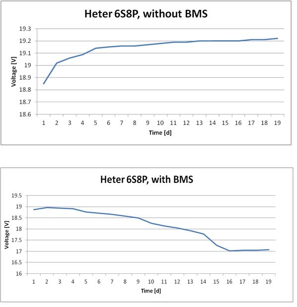

Regards,

RVG

  • From the pictures it looks like the cell voltages will recover significantly after load removal, and that the BMS board provides some time or voltage dependent load that is removed at day 16.  Possible root causes:

    • Unexpected load current
    • Leaking component: capacitor, etc
    • Wrong component value causing conduction
    • Damaged IC
    • Unexpected IC operation

    Unfortunately you will have to test to find it, all is speculation until it is found.  But since your battery has substantial capacity, the load may be large and easy to find.  The following thoughts/questions may be helpful in your investigation. You may get clues from the individual cell voltages after the test, or the state of the BMS board at the start and end of the test.   If low cells have low voltages, look for a current into the IC cell monitor pins at and below the point of low cell voltages. If your '910 shut down due to UV at day 16, this may explain the rise in pack voltage after that time. If it was shut down before the start of the test, you may be looking for some other condition. A good place to start is the voltage across filter resistors indicating current into the IC or board.

    A significant voltage across a VCn input filter resistor likely indicates a damaged TVS (if used), leaking capacitor or damaged IC.  If a TVS is used, check if the proper part is used.  TVS diodes may be rated for breakdown voltage or working voltage.  The wrong one may give a leakage, but may not cut off definitely like your second picture.  If one cell has current into one VCn and out the next, could that one cell be getting drained to a diode voltage drop?  This could be due to excessive differential voltage on the IC shorting the pin pair.

    Check the voltage across the BAT filter resistor.  If it seems out of line, determine if the current is going into the filter cap (we have seen these leak), the TVS, the board, or the IC. The cap, the TVS and the IC might all be expected to have a voltage dependence, perhaps the IC most apparently due to shutdown.  Does the current correspond to the voltage drop on the cells?

    If the current goes into the IC, does it change at the day 16 voltage condition?  If yes, when operating, does it go out DCAP, CCAP, DSG, CHG, VREG or VSS?  A leaking capacitor on CCAP, CCAP, or VREG will cause the current to be drawn from  the BAT pin.  Is there a resistor installed in place of a cap?  If there is a limiting zener on DSG or CHG below the part's regulated voltage, it will draw current from BAT and push out the FET drive pins trying to hold up the pin voltages.  Could one of the FET gates be shorted (do the FETs switch)?  Is there a load current on VREG?  Does something hold up ZEDE causing the thermistor to be powered most of the time? 

    RLDRM_DET is a leakage path by design if the pack is in fault with a loaded output, but should be small, you do not indicate a short condition, and would be constant rather than switchig off at 16 days.  For series FETs the IC supply current can increase with FETs off and CPCKN floating as shown in shutdown current specs, but this would not be expected to appear at shutdown/fault if that is at day 16 rather than go away.

    If you have transient protection parts, are they the proper voltage rating to not leak, and the proper power rating to not be damaged by the system transients and then leak?  If you don't have transient protection, is the IC damaged & leaking BAT to VSS?

  • Hi WM5295, Thanks for the feedback. The test was actually done with the EVM, not iwn developed board. Has there been any feedback on similar findings using the EVM? Thanks. Regards, RVG
  • The EVM should be subjected to the same analysis.  Some possibilities may not apply, for example by default, the EVM is series parallel FETs so CPCKN can't float and there are no zeners on the charge & discharge FET gates. 

    One feedback on the EVM is that if the CHGCTL is held high with a 15k resistor continuously as shown in figure 1 of the user guide, cells will be drained over a relatively short time.  For a 1Ah 10 cell pack, it is ~40% of the capacity in a week.  Continuous connection of CHGCTL out of a charger is not desired, the user guide may not make this clear.  The voltage drop from this type of load is most apparent near the end of discharge, but it also does not go away with IC shutdown.

    The EVM could have any of the manufacturing defects suggested.  It should have passed a functional test, but that test may not catch a higher than normal current.  The default EVM is configured for 10 cells, certainly one area to look at is any modification to support 6 cells looking for unexpected discharge paths. The pack level transisent protection components are relatively large to be easy to work with and hopefully survive an unknown use environment, however they may not be adequate for an 8P cell configuraiton.

    There are test points on the EVM to easily measure across the input resistors.  The jumper can be removed from J1 to measure a voltage representing the current into (mostly) the IC BAT pin.  The TVS and bulk capacitor are before the measurement shunt.  Given the unexpected performance, it may be desirable to measrue the shunt resistance.