This thread has been locked.

If you have a related question, please click the "Ask a related question" button in the top right corner. The newly created question will be automatically linked to this question.

BQ77908A Questions

Other Parts Discussed in Thread: BQ77908A

I want to preface this post with I have not worked with a charge controller before so there's a couple of questions in general as well as specifics about the chip.

The design I'm working on contains solar panels to charge 3 Lithium-Ion batteries in series that will be connected to various loads 

1. In the datasheet, Figure 14.  I want to be sure my assumption is correct in that, if the chip detects an overcharge, it will disengage the charge line, but will still allow the batteries to discharge.  Then for an undercharge, the discharge line will disengage, but the battery will still be able to be charged.  Is my assumption correct?

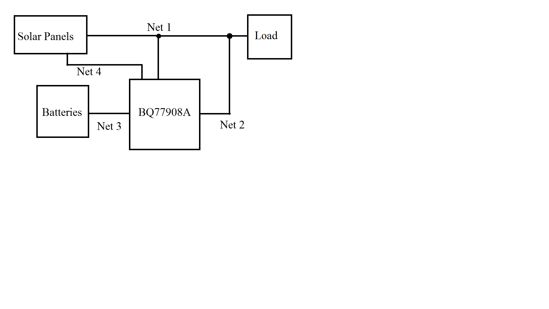
2. I'm a little lost on the connections of the PACK(+) rail and the CHG(-) and DSG(-) rails.  Attached is a crude block diagram.  With this design, the load will be able to draw voltage from the solar panels when they are active or from the battery when they are inactive.  So "Net 1" would be connected to the PACK(+) rail. "Net 2" would be connected to the DSG(-) rail.   "Net 3" will be the connections to VCX. Lastly, "Net 4" will be the CHG(-) rail.  Is this how the chip would work?  

3. Since we are only using three batteries in series, then the most positive battery will be connected to VC7 and the lowest will be connected to VC9, with VC1-6 tied to VC7.  Is that correct?

  • To jump to #3, the bq77908A would not be suitable since it only supports 4 to 8 series cells. TI does have a number of battery management devices for 3 cells which may be useful in your system, information may be found at www.ti.com/battery .  The following may be helpful:

    1. Most faults will turn off both FETs.  See datasheet table 2.  OV will turn off only the charge FET and UV will turn off discharge FET but leave the charge FET on if CHGST is high.  When using the figure 14 circuit, be certain that the charger can't allow discharge and the load can't allow charge since the paths are separated.  The figure 14 circuit is most often considered where the current flow is known/controlled and the load current is much higher than the charge current.

    2. In general yes.  The cells must have a path to the current through the protection switches of course.  Additionally you may still need a charge controller from your solar panels to regulate the output and prevent discharge into that circuit. Many other BMS devices will support the 2 terminal configuration like figure 13 so that the battery is protected regardless of the current direction.

    3. The bq77908A can only support down to 4 series cells. If you had a 4 series cell system the monitoring inputs would connect through the filter:

    • Battery negative would connect to VC9
    • The lowest cell positive would connect to VC8
    • The second cell positive would connect to VC7
    • The thrid cell would connect to VC6
    • The fourth cell would connect to VC5,
    • A resistor should connect from VC5 to  VC1 - VC4