This thread has been locked.

If you have a related question, please click the "Ask a related question" button in the top right corner. The newly created question will be automatically linked to this question.

LMR14203 burns

Other Parts Discussed in Thread: LMR14203

I am using LMR14203 to supply 5V 80mA from 24V input.

Actual 5V consumption is much less (~30mA).

Design and components according to Webench.

Sometimes, on power up, the LMR14203 burns.

It happens immediately, with smoke.

Please advice.

  • Hi,


    Can you send some more information to help us diagnose the issue?

    1)  The schematic you are using

    2) A scope shot of your 24V rail when you power up, with the probe placed close to the input pins of the LMR14203

    3) Pictures of the LMR14203 layout within your design.


    Thank you

  • Please send the schematic and PCB files

    FD

  • Attached please find a Word file with schematics description, and a PCB file with layout.

    I couldn't check the 24V on the board, as the LMR14203 is currently a short circuit. I have checked on the power supply, and it takes about 8mS to rise from 0 to 5V (and continue).

    As I currently using a laboratory power supply, I assume the load does not change.

    0878.Phase2_9-12-13.pcb

  • See answer to  Marc Davis-Marsh, in this issue.

  • OK, I am looking at the PCB file.  Can you re-attach the word file with the schematic.  I don't see it in the posts.


    Thank you,

    Marc

  • Hi,


    I took a look at the schematic and th PCB layout.

    I have two comments.

    1) The 24V trace to the LMR is fairly long.  The inductance from this trace might be resonating with the input capacitance due to the negative input impedance of the buck converter.  If this is the case you will see oscillations at the Vin of the part.

    2) The ground of C11 should be directly connected to the ground of D1.  This will improve the bypassing and decrease noise seen on Vin and the switch node.

    That said, I am not sure if those two things are enough to see the device damage you are seeing.

    When you get another part mounted, could you measure a few things.

    First try lowering the supply voltage to 12V to give us some more margin.

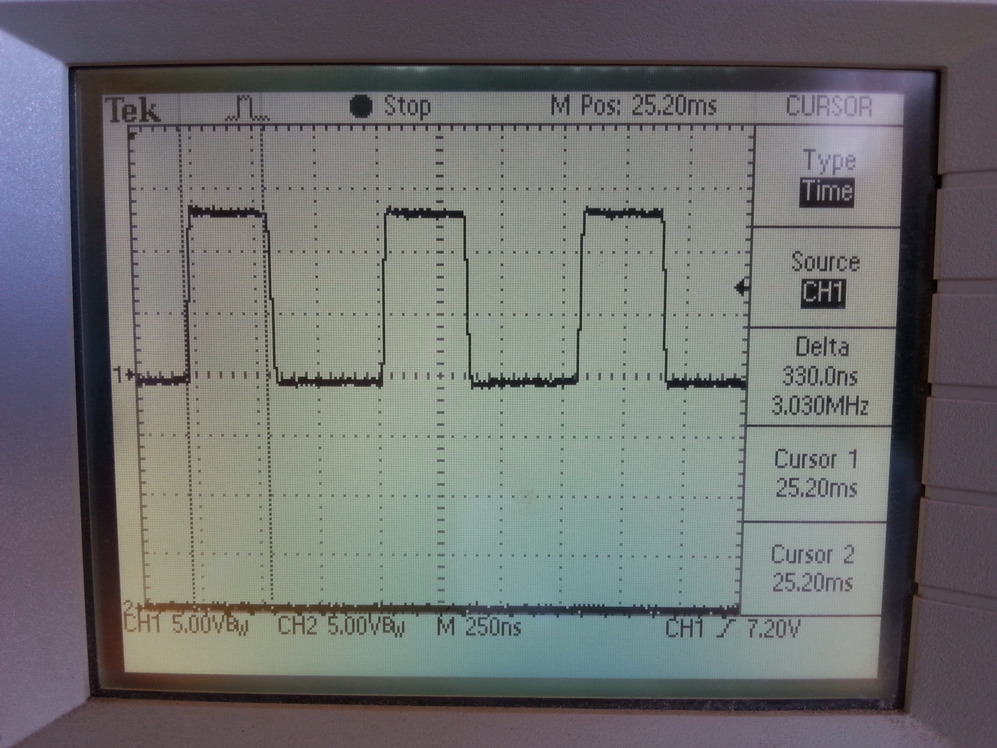
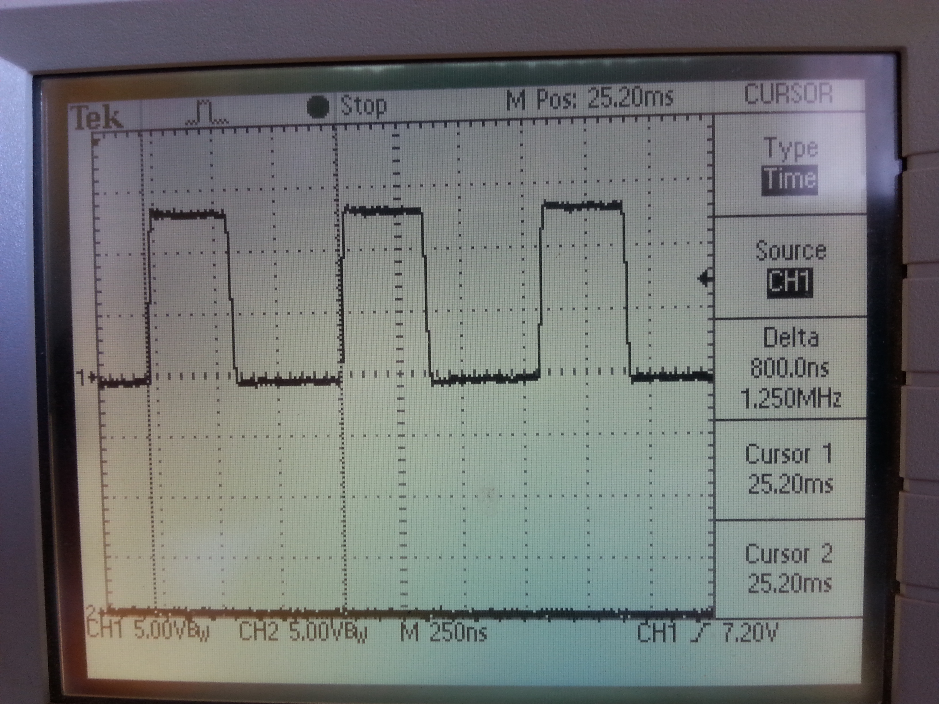
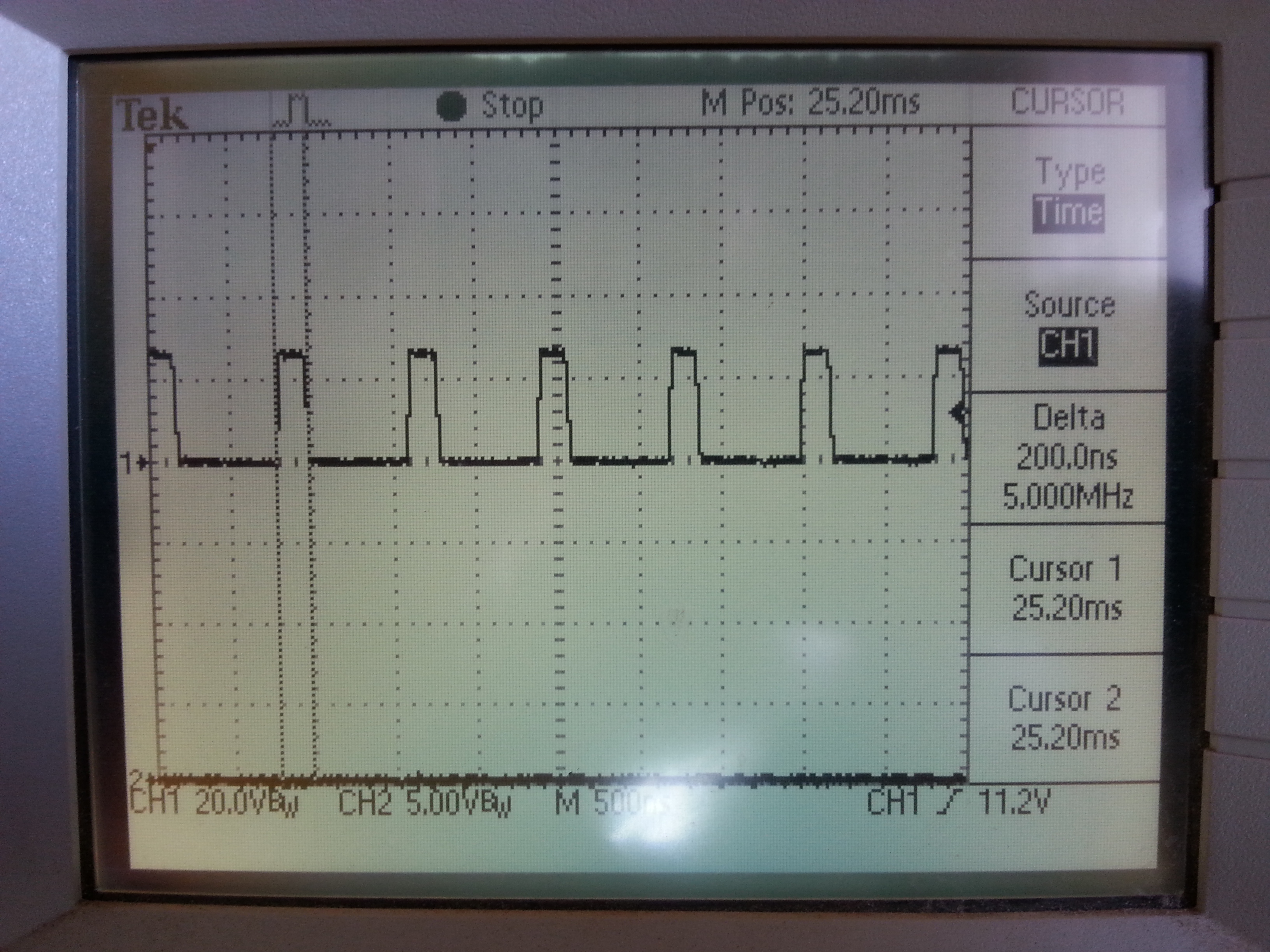
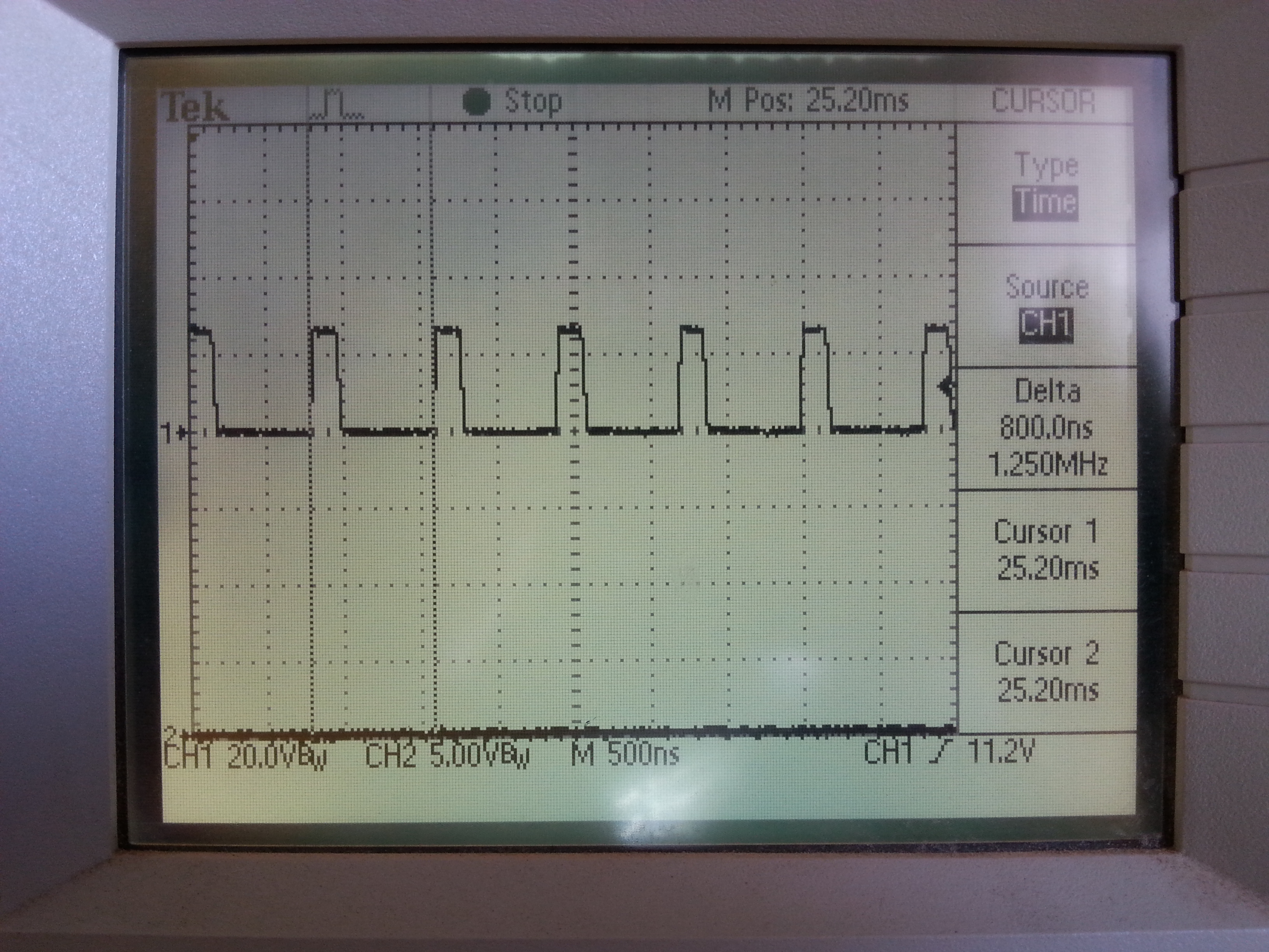
    Then look at the Vin and SW pins to see if there is excessive ringing.  If there is then we might have located the problem.  If not then we need to look elsewhere.

    Regards,

    Marc


  • Hi Marc,

    Thanks for your reply.

    1. C11 is directly connected to D1 and U2, through vias to ground plane in top layer.

    2. I have lowered the voltage to 12V (possible only in the lab), and checked Vin and SW.

    3. Vin: 5-7mV noise (on 12VDC).

    4. SW: See attached files (see cursors measurements)..

    5. I didn't test in 24V, as I am currently short of components (and, have to finish the firmware for yesterday...).

    6. I had three cases of burning LMR14203, and as I remember, all of them happened in power up.

    Gal

  • Sorry, I should have mentioned to take the switch node measurement with the higher bandwidth so I can see if there is excessive ringing.

    Questions/Comments

    1)When you were looking at Vin did you have a load on the LMR?  If you do end up seeing ringing

    2) On the schematic you had a 30V TVS.  I have seen cases where if this diode triggers it can pull current back through the body diode of the high side fet.  Because this current is uncontrolled it could be very high.  You might want to add a diode after D1 to prevent this possibility.

  • Hi Marc,

    1. I have tested in 24V. (power up in 12V, and than raised the supply to 24V).

    2. Noise on Vin: 10mV.

    3. SW: looks OK. See attached.

    4. All done with load (~20-30mA). The same load in the events when LMR burned.

    5. Adding a diode: see attached. Is this what you mean?

    6. I can add the diode. But, as these tests can be "destructive tests", and I am short of LMRs, I will do it after checking all other ideas.

    Gal

      3771.TI_LMR14203_2014-01-30.docx

  • Hi,


    Yes that is what I meant with the diode.

    I agree that you should be careful with the input voltage and finish your tests before adding it in.

    Let me know if the problem still occurs when you restart your power supply testing.


    Marc