This thread has been locked.

If you have a related question, please click the "Ask a related question" button in the top right corner. The newly created question will be automatically linked to this question.

Trying to decide on the best battery charger...

Other Parts Discussed in Thread: LM3463, BQ24618, BQ30Z554-R1

Good Morning TI!

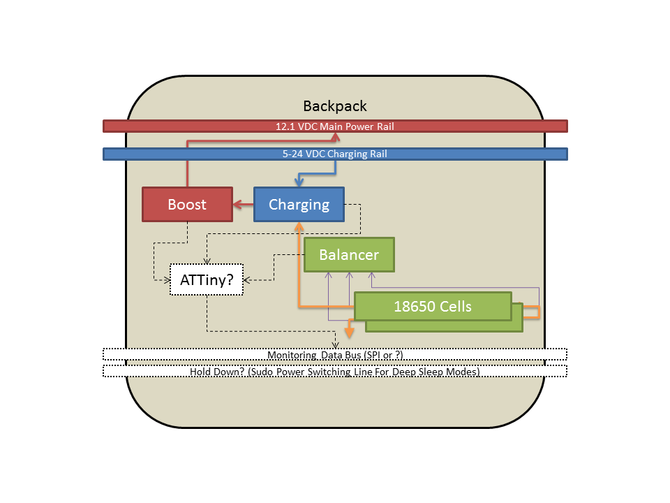
I am having a tough time finding the right chip for my application.  My project is just on paper for now until I get a good grasp on the components I need.  I am working to build a modular flashlight and one thing I thought I wanted to do was build stack-able "battery packs".  The battery packs would mate end to end and provide a common 12VDC rail for the flashlight head and have a common xxVDC rail for charging that comes from an external source at the butt end of the flashlight.  That means each pack would have its own charging circuit and its own boost circuit (to achieve the 12VDC rail).  The goal is to take a PCB and mount two 18650 LiPo's on the back with all the circuitry on the opposite side. 


What I would like to see in my charging circuit is 2-cell active balancing during use and during charging, ability to adjust for temperature, and being able to accept 12VDC charging.  Bonus would be a 5-24v charging.


Suggestions, mindset changes, and crazy talk are all welcome.  Thanks!

V/R,

Frank

  • Hello Frank,

    If I am understanding this design correctly you are wanting to make battery modules that consist of 2 18650 cells and a selection of other power circuitry. These packs will then connect to a main rail to provide boosted power to the light. Will they be charger off the same electrical connections that they use for discharge?

    How are you wanting to configure these 18650 cells? Will they be in series or in parallel? If they are in parallel you will not need balancing. Those would also make it easier to find a charger that would have the extended range you are requesting.

    Could you clarify what you mean by adjust the temperature?

  • Ryan May said:

    Hello Frank,

    If I am understanding this design correctly you are wanting to make battery modules that consist of 2 18650 cells and a selection of other power circuitry. These packs will then connect to a main rail to provide boosted power to the light. Will they be charger off the same electrical connections that they use for discharge?

    How are you wanting to configure these 18650 cells? Will they be in series or in parallel? If they are in parallel you will not need balancing. Those would also make it easier to find a charger that would have the extended range you are requesting.

    Could you clarify what you mean by adjust the temperature?


    Ryan,

    Thank you for your time to respond to this thread.  You are correct in that I want to utilize two 18650 cells per pack and the "backpack" PCB will contain the charging circuit and a common rail to the light.  Based on some of the two cell charging circuits I saw, the plan was to put the charger rail separate and allow the charging circuit to bridge as necessary to the boost circuit that supplies the common rail to the light.  I would consider parallel 18650s for the task however I was trying to keep my foot print small by taking Vbatt and getting it closer to the rail voltage. 

    I have included a functional diagram of what I was looking to do.  The goal would be to daisy chain these backpacks end to end in the body of the flashlight.  It is likely to be limited to four based on 1. SEL lines for any SPI monitoring, 2. PCB traces for current (see next paragraph), and 3. amount of charging current needed if the desire is to operate the light while charging.

    I desire that the flashlight head use six Cree MK-R's which each run at 12.1VDC for 1000mA of current for a nice 200 lumnes/watt.  I would drive them with the LM3463 five channel constant current controller. Coupled with an Arduino uC, I have the ability to control the lights how I see fit and monitor the backpacks for errors.  I want to incorporate a control ring around the housing and utilize your new induction sensing circuits and use the control ring to change modes and change brightness (slide axially to change mode and rotate axially to change brightness... the ring would be divoted to allow for detents using a ball and spring).

    Thanks for the help!

    Frank

  • Hello Frank,

    Sorry for the delay.

    I would think that the BQ24618 would be a good place to start. It is USB charging compatible, capable of charging multiple cells, and can take an input voltage up to 28V.

    Would you be using load switches to decide whether you are charging or discharging?

    Also have you selected a gauge & balancer?

  • Ryan,

    Thank you for the suggestion.  I will take a look at it.  I have not selected a gauge & balancer yet and I am all ears.

    Thanks,

    Frank

  • Hello Frank,

    Looking through some of your requirements there are few more things that would be needed to narrow down a gauge.

    What is the capacity of the your 186500 cells?

    How accurate do you need your tracking to be?

    I am assuming that solution size is critical and finding the smallest possible chip set is a goal.

    A device like the BQ30Z554-R1 has internal balancing and uses Impedance Track for accurate cell tracking and management.

    On another note for your system:

    Would the microcontroller be used to control a load switch to selectively drive the boost converter to protect the battery and the system?

    I would recommend looking into secondary protection in addition the to the gauging and balancing.