This thread has been locked.

If you have a related question, please click the "Ask a related question" button in the top right corner. The newly created question will be automatically linked to this question.

LM3410

Other Parts Discussed in Thread: LM3410

Hello,

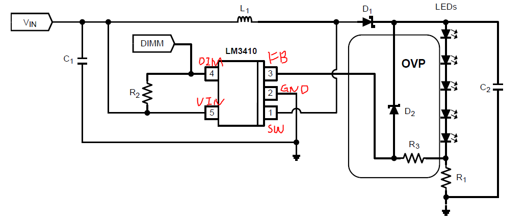
I am interested in using the LM3410 in an automotive application, but not for driving an LED. I am looking to utilize this component or (anything else that may be suggested) to drive a proportional valve. The valve will draw between 0-900mA (based on PWM input), and the main reason for wanting to use an LED driver is the constant current capability. As is normal for inductive loads (motors and solenoids) I plan on placing a diode in parallel with the valve to protect against inductive feedback into the component. Is this component suitable for my application?

Thanks in advance,

Adam Ambriz

  • Hi Adam,


    Thank you for your interest in LM3410.

    The device should work well if you have correct input and output configuration.The maximum switching current is 2.8A. So if you are using a 5V as input, the maximum output voltage will be around 13V assuming the efficiency is 85%. For the output over voltage protection, you may refer to the LM3410 data sheet figure 18.

    Best regards,

    Victor

  • Victor,

    Thank you for your response, I have purchased a few LM3410s (the 8 pin MSOP package) to test. Looking over the datasheet, I wanted to make sure I was understanding things correctly. Pins 3 and 2 should be my Power and Gnd connections respectively, (with a decoupling capacitor). Pin 4 should be my PWM signal for controlling current delivered. Pin 5 should have a Resistor network attached between it and pin 6, and pin 7 should be my proportional valve output connected to the resistor network at pin 5, with a diode in parallel to protect the IC.

    If all this is correct, does my Rset value need to be selected to allow for maximum current (1A) when the PWM duty cycle is 100%? Also what value inductor do I need also. Thanks again for your assistance.

    Regards,

    Adam

  • Hi Adam,

    What is your input and output voltage? The LM3410's input voltage range is from 2.7V to 5.5V. You put a 12V as source in your schematic. You may use the schematic I attached as reference.

    The Rset value is determined by maximum LED current while the inductor value will be determined by several parameters including Vin, duty cycle, switching frequency you choose and inductor ripple. For detail instruction, you may refer to data sheet pg.11 and 12.

    Best regards,

    Victor

  • Ah, yes my input will be between 2.7-3.3V. If I want my output voltage to be roughly 12V, with a current of 1A, does that mean I need a 12W, 12 Ohm Resistor?

    -Adam

  • Then I think you can't do with LM3410 as the maximum switching current is 2.8A and in your case the switching current will be around 4A.

    Regards,

    Victor

  • Is there another LED driver more suitable? Or perhaps another IC which will provide constant current?

    Thanks again for all your help.

    -Adam