This thread has been locked.

If you have a related question, please click the "Ask a related question" button in the top right corner. The newly created question will be automatically linked to this question.

Offline Push-Pull with UC3825 PWM Out Problem

Other Parts Discussed in Thread: UC3825

Hello Friends,

I designed a 300W SMPS with Push-Pull Topologies.

Features:

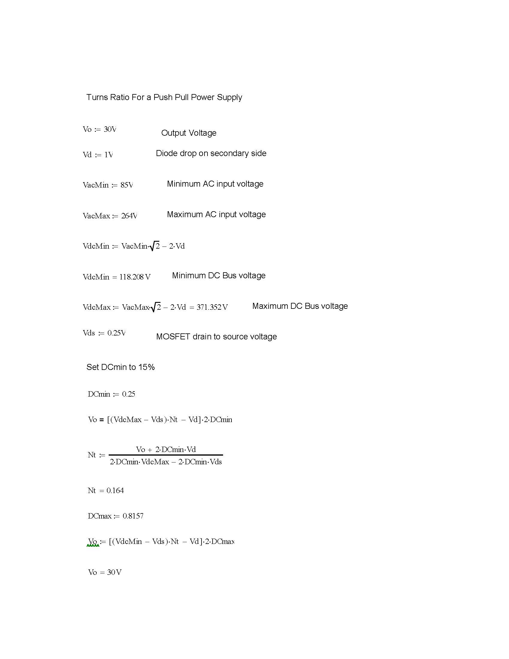
Input Voltage: 220V AC/ 50Hz

Output Voltage: 30V/ 10 A
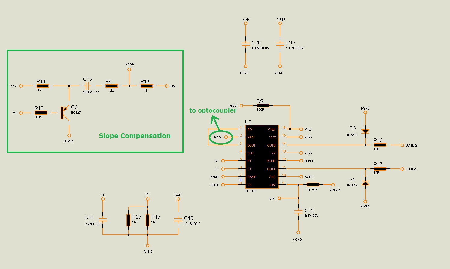
PWM IC : UC3825


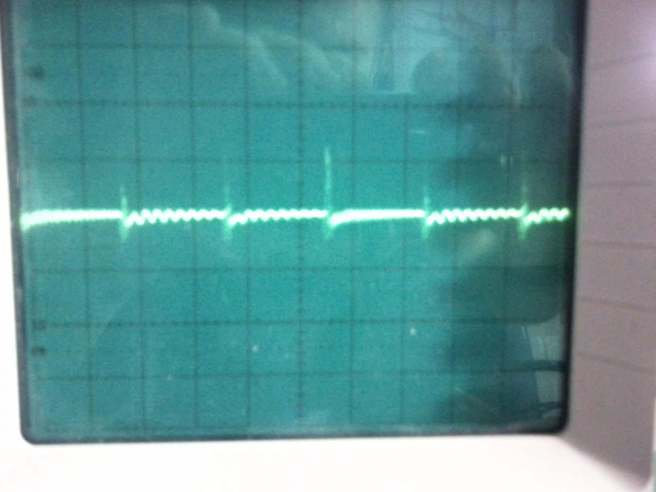
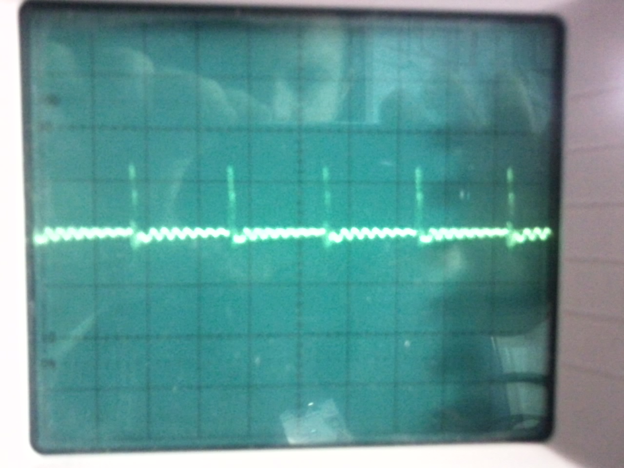
However, I have a serious problem. Output voltage is normal. I can adjust with trimpot(feedback is normal), no problem. But UC3825 Pwm Out Signal's are very distorted. I have added pics. (OUTA and OUTB signals and Control Stage.) 

(Oscilloscope pics features: 5 Volts/Div, 5 us/ Div)

Does anyone have an idea?

Best regards.

Important DATA: If I apply voltage 100VDC and less than, PWM out signals are excellent. But if I apply voltage greater than 100V DC, Pwm out signals are very distorted and duty time is decrease as the pics.

  • Emre,

    Just on the basis of what you have said and the scope plots, I would guess that the transformer turns ratio is too high. If you are designing for 220 VAC your DC bus voltage should never see 100 VDC and if the PS works fine at that input voltage the transformer ratio is too low. You should have an undervoltage lockout that prevents the PS operating at that low of voltage anyway. Since the circuit should be optimized for high voltage operation, operating at 100 VDC should cause high duty cycle and high input currents.

    I have enclosed below a mathcad example of how to calculate the proper push-pull transformer turns ratio, if that is your problem.

    Hope this helps,

    I can send you the mathcad file if you want it.

    Chuck

  • Hi Chuck,

    Firstly, thanks for your answer.

    Yes my rated voltage 220V AC. But I apply input voltage 100V DC for find the problem. I used Variac(Autotransformer) and I adjusted this voltage. 

    I want to share some info to you;

    Turn ratio of my first transformer design: 0.192  (If input voltage is higher than 100V DC, duty cycle is decrease)

    Turn ratio of my second transformer design: 0.152  (If input voltage is higher than 170V DC, duty cycle is decrease)

    Turn ratio of my third transformer design: 0.066  (If input voltage is higher than 350V DC, duty cycle is decrease)

    The input voltage response of my Push-Pull design is  progress as can be seen in the above. I used ideal transfer function eqution for third transformer design by Texas Instruments Power Supply Topology Poster.

    What do you think about it, now?

    Regards,

  • Hello Emre,

    It sounds like you thought a lot about the turns ratio and that is not the problem. If you calculated the turns ratio based on a TI design guide, I am sure that's fine. My number for the turns ratio is a litter higher The number I had for the turns ratio is only a little off from the ratio you calculated in your first and second design. The difference is probably due to the diode drops or the MOSFET Vds.

    The only thing I can think of that could be a problem is the number of turns on the primary is too low to support the primary voltage and the input primary voltage is collapsing. An easy check is to measure the outputs of your transformer secondaries and verify that the ratio and the magnitudes of the secondary to primary voltages are correct.

    I have set of design equations for a push-pull transformer that I have used in the past successfully if you need them.

    Good luck,

    Chuck

  • Hi Chuck,

    I will measure primary and secondary voltages and I will tell you about conclusion and verifying.

    If you can send push-pull design equtions, I would be very happy. Then, I will share my design equtions with you.

    Thanks,

    Regards,

    Emre.

  • Emre,

    I think I know the problem with your design. Your transformer may be saturating. Also, my duty-cycle calculations will not work because they go beyond 50%. If you have a 375 volt rail, you need to be using 1000 V MOSFETS. The problem with the push-pull design is described below. This comes from the NXP handbook on power supplies:

    "One of the main drawbacks of the push-pull converter is
    the fact that each transistor must block twice the input
    voltage due to the doubling effect of the centre-tapped
    primary, even though two transistors are used. This occurs
    when one transistor is off and the other is conducting. When
    both are off, each then blocks the supply voltage, this is
    shown in the waveforms in Fig. 11. This means that TWO
    expensive, less efficient 800 to 1000V transistors would be
    required for a 220V off-line application. A selection of
    transistors and rectifiers suitable for the push-pull used in
    off-line applications is given in Table 4."

    (The paragraph below may explain the problem with the transformer.)


    "A further major problem with the push-pull is that it is prone
    to flux symmetry imbalance. If the flux swing in each half
    cycle is not exactly symmetrical, the volt-sec will not
    balance and this will result in transformer saturation,
    particularly for high input voltages. Symmetry imbalance
    can be caused by different characteristics in the two
    transistors such as storage time in a bipolar and different
    on-state losses."

    If you are using current-mode control you may be ok with the flux imbalance, but using current mode usually means you have to limit your duty cycle to a maximum of 50%. So the duty cycle calculations I gave you are wrong. That is unless you have a special PWMIC that can detect flux imbalance, then maybe you can use push-pull at high input voltage and high duty cycle.


    "The centre-tap arrangement also means that extra copper
    is needed for the primary, and very good coupling between
    the two halves is necessary to minimise possible leakage
    spikes. It should also be noted that if snubbers are used to
    protect the transistors, the design must be very precise
    since each tends to interact with the other. This is true for
    all symmetrically driven converters."

    I think you need to change your SMPS topology:


    "These disadvantages usually dictate that the push-pull is
    normally operated at lower voltage inputs such as 12, 28
    or 48V. DC-DC converters found in the automotive and
    telecommunication industries are often push-pull designs.
    At these voltage levels, transformer saturation is easier to
    avoid."

    Hope this helps. I will send you the push pull design equations you asked for sometime today.

    -Chuck