This thread has been locked.

If you have a related question, please click the "Ask a related question" button in the top right corner. The newly created question will be automatically linked to this question.

TPS65146

Other Parts Discussed in Thread: TPS65146

HI,

im using TPS65146( IC LCD supply TFT 24-VQFN) to provide required supply voltages to run 7 inch LCD panel so i used a 24-VQFN breakout board with IC ready assembled and i just added the discreet components, but unfortunately it did not work and the VS out that i got was the same as input (3.3V) instead of 10.4v,and all other voltage were also nither 3.3v or less, so please advice what is the problem and how to troubleshoot it, following is the schematic I've used:

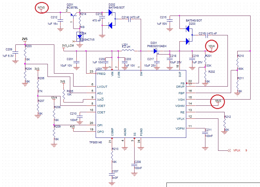
knowing that the required supply voltages are:

1. VGH=16V

2. VGL = -7V

3. VS = 10.4 

4. VCOM = 3.8V

thanks in advance

  • Hello Shadi,

    To be honest, a power supply layed out on a breakout board will almost never work. For switch mode power supplies the layout is an essential part of the design, especially the GND connections have to be layed out the way that there will be minimal GND shift between the IC and the external components.

    If you still want to debug your design, you need to check first if you get the 2.5V on LVOUT. Only if this voltage is available, the other outputs are allowed to start. In addition you need to check the startup of the board with an oscilloscope. All voltages need to be measured when you apply the input voltage. You need to check as well the input voltage itself because during startup a current peak will happen on your supply which might cause the IC to fall again into UVLO.

    But to be honest, I would recommend to generate a layout that follows good power supply layout rules.

    Best regards,
    Brigitte

  • Hello Brigitte,

    thanks a lot for your response, now i will follow your recommendation and update my results.

    thanks again