This thread has been locked.

If you have a related question, please click the "Ask a related question" button in the top right corner. The newly created question will be automatically linked to this question.

BQ24090 charging issue (CHG LED not turned out, pulling the current from OUT pin, waveform strange)... HELP NEEDED!

Other Parts Discussed in Thread: BQ24090

First of all, I am using BQ24090EVM-001 evaluation boards, which I set the RISET = 1 kOhm (current is around 540 mA); Enabled TS with simple 10 kOhm resistor (no TS function or connection to the battery); ISET2 set to follow whatever ISET is; Also, enable CHG and PG LEDs function. I have tested two BQ24090EVM-001 boards and the issue happens on both of them so that I believe I could rule out the chance of anything wrong with the board.

I have developed a product powered by single cell Li-ion battery. The charging function is monitored by one mcu (inside the product). This mcu controls the open and close of MOSFET to control the charging function.

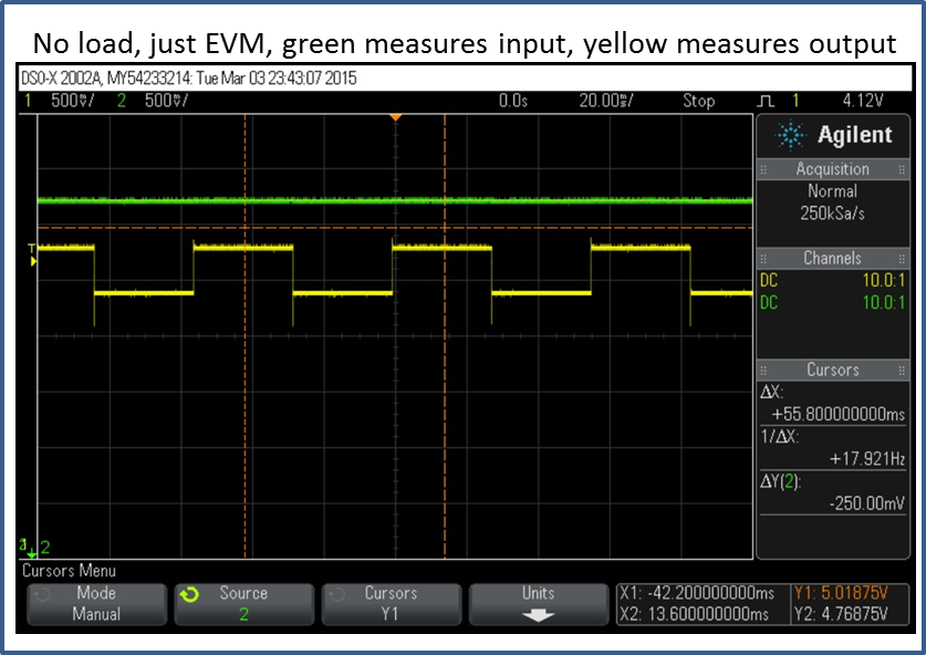
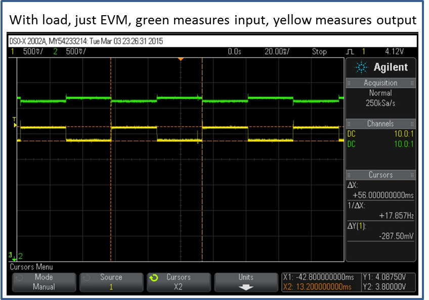
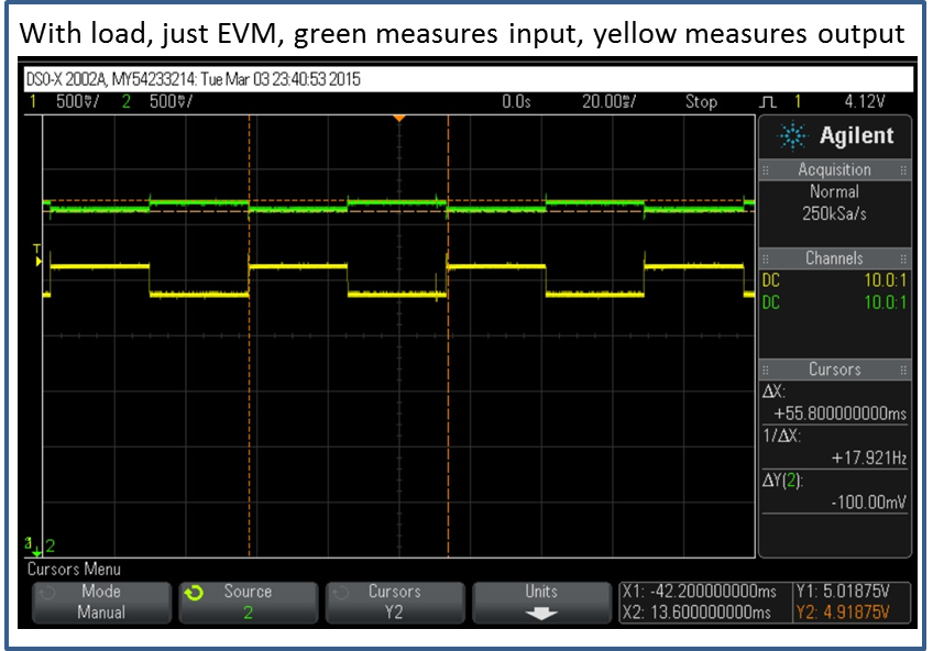
I am testing the charging for this product using the evaluation boards. Occasionally, I could find the charging is abnormal: Once connect the evaluation board OUT and GND to the product charging pin (positive and negative), 1) the CHG LED never lit up; 2) scanned waveform on the charging pin of the product shows a square wave with 18 Hz frequency and 100 mV amplitude (the frequency happens to be the same as battery detection mode, except the square wave in battery protection mode is from 4.2 V to 3.8 V.); 3) the current is actually drawn from the OUT pin if measure with DC power supply, however, the current value is from 100 mA or so to 300, 400 mA, fluctuating, not stable 540 mA if function correctly (with CHG LED on).

The PG LED always lit up during the process. 

Strangely enough, the above phenomenon happens occasionally, with no pattern found. Like 80% of the time, it is charging just fine!

If I had a chance capture this on my scope, I will post it here.

Can anybody tell me what is going on? Is it a problem with the chip or somehow it is due to the design?

Thank you.

  • Can you provide additional information below?

    - What is the input voltage voltage when this is happening?

    - I understand you saw the 18 hz square wave. Is it from 0 to 100mV or something else?

    - Besides the battery, did you have any other load connected to OUT pin?

    Looks like the output is not able to turn on correctly and it could be caused by input DPM. It is a mode in which input cannot provide enough power to satisfy the needs from output, so the input voltage will drop and current will reduce. Sometimes inrush current from output can also cause DPM so if possible please check if this is the case when you plug in the battery or load on OUT pin.

    Thanks,

    Wenjia

  •  Wenjia,

    Thank you for the reply.

    Here is more information:

    - What is the input voltage voltage when this is happening? Ans: The input voltage is interestingly fluctuating around 5 V (4.9 V to 5.2 V, square wave, same frequency as OUT fluctuating).

    - I understand you saw the 18 hz square wave. Is it from 0 to 100mV or something else? Ans: No, it depends on the battery cell voltage. The last measurement I made: battery cell voltage is 3.8 V (measured not charging), maybe 3.9 V when charging. The fluctuation is from 3.86V to 4.03 V (measured when charging).

    - Besides the battery, did you have any other load connected to OUT pin? Ans: I have a system load connected to OUT pin when charging. The load may drain 12 - 13 mA from the battery (one mcu, two LEDs and some system error estimated).

    What I managed on charging is as follows: when charger is plugged in (connect OUT pin and GND to the product charging port), mcu learned the charger is plugged in and switch the mcu power supply from battery cell to charging port (through MOSFET control, system load is draining 12 - 13 mA from OUT at this moment). Then, the product will wait 5 seconds for everything settling down and then open the charging MOSFET. Charging process is starting now (OUT provides current to battery AND system load 12 -13 mA).

    I have posted a scope pic when this happens. The green line is measuring the input voltage into the IN pin of 24090. The yellow line is measuring the voltage into the product charging port (a 40 cm long wire is connecting the OUT pin and charging port).

    Do you think it might relate to the contact resistance somehow? If I am using shorter wire, the waveform behaves much better. However, the 40 cm wire should not post much resistance on the line.

    Please let me know if you have any idea. I am really at loss. Thanks!

  • Just to clarify, since the pic effect is not so good. The curve on the top is input voltage measurement and the curve on the bottom is measuring the voltage at charging port of the product. The curses are set to measure input voltage.
  • Wenjia,

    I have looked into the issue this weekends. I guess I found something but I am not sure it is coincidence or THE root cause. Is it possible a bad contact between charger output and product charging port could raise such waveform? The connection is magnetic and if I found such waveform, I just twisted the charging head and the square wave went away, and CHG LED is on (OUT current is stable, read from power supply, I use DC power supply as the power source for the experiment so that I could have a sense of the charging current).

    So here is the question: if there is a contact resistance, is it possible for BQ24090 to output such strange waveform?

    Btw, I tested the in-rush current, if the capacity of the battery cell inside product is low (I used a 1.5 V Li-ion cell), the in-rush current is high (as high as the set fast charging current), I guess the capacitors inside product (22uF) need to be charged full upon connection. However, that does not cause the strange output waveform issue. I could just charge fine with a low capacity Li-ion cell and the whole system. If the cell voltage is normal, the in-rush current is small, just 30, 40 mA initially.  

    Thank you.

  • Yinjun,

    The contact resistance of the wire will definitely impact both the input and output signal greatly. There're mainly three possible impacts.
    - The line resistance on input can cause big voltage drop from the power supply to the VIN pin and once the VIN voltage drops to VIN_DPM, the output will be zero ( without a battery).
    - The line resistance from OUT pin to battery can cause big voltage drop so that the charging will terminate early because the OUT pin voltage will be higher than the actually battery voltage.
    - The parasitic inductance of the long wire can form a LC circuit with the on board capacitance and cause oscillation at output. Twisting the wire and adding capacitance at OUT pin can effectively reduce this impact.

    Therefore, I think what you did is helpful. In addition can you let me know the below information?
    - Can you measure the input voltage without connecting the product? I want to make sure the input signal itself is stable.
    - What is the capacitor value at OUT pin? Can you try increasing the value and see if it helps?
    - If you pull TS pin high, will you still see the waveform?

    Thanks,
    Wenjia
  • Wenjia,

    Thank you for the reply. It has been a while and I did a few tests you asked. Here I will show you the results:

    - Can you measure the input voltage without connecting the product? I want to make sure the input signal itself is stable.

    ANS: I use DC power supply (5V and 1A output, it is a Tecktronix product... So it should be reliable.). Anyway, I put the oscilloscope graph here. I use a standard BQ24090EVM-001. Green measures the input into the EVM board; Yellow measures the output from the EVM board OUT pin without any load / system.

    - What is the capacitor value at OUT pin? Can you try increasing the value and see if it helps?

    ANS: I use a standard EVM board from TI. The capacitor is 2.2 uF according to the schematic and my measurement. I have not tried increased the value but I do not think that will help... Please continue reading and I will show why.

    - If you pull TS pin high, will you still see the waveform?

    ANS: After I pull TS pin high, the waveform has not occurred yet. Maybe we just solve the problem? Interestingly, I found the battery detection pattern is disabled. Is this normal? What is the downside of TTDM, except that I can not measure the temperature on the battery (which I do not measure anyway)?

    I have also taken a few scope pic on the problem I had before, which I believe has something to do with the contact between OUT and system/battery. Channel 1 is yellow color line, which measures OUT of 24090. Channel 2 is green color line, which measures IN of 24090. The below two graphs are measuring with battery and system load. They are the same screenshot with cursors measuring different channels (see bottom right corner on the graph).

    Here is another question: why does that happen and why could OUT and IN somehow synchronize in this pattern, though IN voltage changes very little?

    Any thoughts? Thank you very much!

  • - When the device is in TTDM mode, besides the TS temperature monitoring function, the battery detection, safety timer and termination are also disabled. I suppose you may need safety timer and termination to be active, so TTDM may not be a good choice for you.

    - The waveform on input and output pin tells me that your output power is more than what the input can provide, so the input voltage dropped when the output voltage is at the higher level. What is your load current? Can you calculate what is the output power?


    Thanks,

    Wenjia
  • Thank you, Wenjia.

    I understand TTDM mode now. I think it will be fine if I disable it since on the device side, I have also implement a safety timer and termination in the mcu.

    The output power is actually low in the graphs I showed you. But I think what you said makes sense.

    I set the output current (fast charging current) equals to 430 mA. When everything is normal (no strange waveform happnes), the output current is 430 mA and output voltage is battery cell voltage which is 3.9 V. When strange waveform is happening (showed in the previous thread), the output current is jumping (which varies from 100 mA to 300 mA, and it is more likely to be random rather than have a certain pattern). The output voltage is between 3.8 V and 4.08 V as shown in the graph.

    It might be the power drain on the output pin is too high which causes the current is reduced from 430 mA (normal value) to smaller number (and this number is also jumping).

    Here is one more question: what caused the power drain change? Since I use the same system and battery, sometimes it behaves normal and sometimes it behaves strange (as shown in graph in previous thread). Could it be the contact on the OUT pin, which equivalently adding a series resistor in the charging loop?