This thread has been locked.

If you have a related question, please click the "Ask a related question" button in the top right corner. The newly created question will be automatically linked to this question.

BQ24650 Questions Design For Lead-Acid Batterry

Other Parts Discussed in Thread: CSD18504Q5A, BQ24650

Hi,

I have design the circuitry of BQ24650 Lead-Acid battery charge controller (2A) by referring to the sluu444a. 

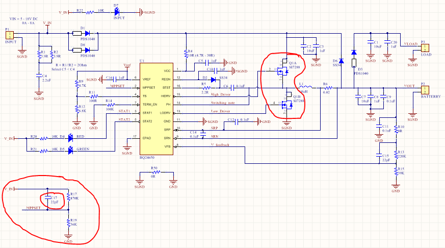
This is my schematic.

I testing with power suply, obtained test values (connected with lead-acid batterry 20Ah)

Vin = 20V; Vcharge = 12.88V; Icharge = 0.57A

Vref = 3.28V; Vts = 1.93V, Vregn = 5.95V

Vfeedback = 1.88V; Vmppset =1.18V

If I increase or reduce Vin then Vmppset; Icharge  & Vfeedback not change. 

I remove batterry, test values:

Vin = 20V; Vcharge = 13.86V; Icharge = 0A

Vref = 3.28V; Vts = 1.93V, Vregn = 5.95V

Vfeedback = 2.05V; Vmppset =1.27V

If I remove capacitor C17 - 22pF (connect to MPPSET pin) or I replace C17 with value 10pF and re-connect Battery, obtained test values:

Vin = 20V; Vcharge = 13.86V; Icharge = 1.96A

Vref = 3.28V; Vts = 1.93V, Vregn = 5.95V

Vfeedback = 2.05V; Vmppset =1.27V


The question is:

1. Can I don't use capacitor C17?

2. Why I using C17 - 10pF, Icharge increase ~2A, using C17-22pF Icharge = 0.57A?

Thanks for help me!


  • You are allowed to use C17. One of two possible things is happening on MPPSET:

    1. C17 has high leakage. This is causing the DC voltage on MPPSET to change.
    2. MPPSET has a lot of noise (because it's tied directly with VIN through a resistor). In this case, C17 is helping to filter out the noise on MPPSET, which is why the DC voltage is different.

    Can you post a waveform for MPPSET with C17 and another waveform without C17 in the circuit?

  • Thank you for your quick reply!

    Here are the waveforms at MPPSET pin:

    1. With cap C17

    - No connect to batterry

    - Connect to batterry

    2. Without cap C17

    - Connect to batterry

  • If you compare the last two waveforms, you can see that the MPPSET has a lot of noise when C17 isn't connected. This means that the average DC voltage at MPPSET is different with and without the capacitor. I recommend leaving the capacitor in there (you may want to play around with the value to see if you get a cleaner signal on MPPSET with a larger capacitor like 100nF).
  • Thank you so much!
    I tried as you said and my circuit operation very well.
    I have one question about the choice of mosfet, can you help me?
    Now, I want Icharge = 10A, can I to use the mosfet SI7288DP?
    Otherwise, You give advice how to use mosfet?
    Thanks again!
  • The Si7288DP will work for this application. However, I recommend the CSD18504Q5A MOSFET from TI. The CSD18504Q5A has a lower Rdson and lower Qg when compared to the Si7288DP. The lower Rdson and Qg will result in lower MOSFET switching losses (for both high side and low side MOSFET) and lower driver IC losses (for both high side and low side MOSFET). By my estimate, the CSD18504Q5A will result in 50% lower switching losses and 23% lower driver IC losses when compared to the Si7288DP.

    Calculations were done using equation 16 through 22 on page 22 of the bq24650 datasheet.

    If you can minimized the ringing on the PH node in your final PCB, then you might be able to use 30V MOSFETs. TI has several single channel 30V N-channel MOSFETs and dual channel 30V N-channel MOSFETs (these dual channel MOSFETs are called power blocks and are optimized for buck converters). Please visit this link for an overview: www.ti.com/.../power-mosfet-overview.page .
  • hi kha pham I am using the same schematic but I am using qfb 20n06 instead of si2788 and i have no voltage at the o/p but all other conditions are mt vfb and ts and vref and vregn I am using a supply of 21 vdc

    also i would like to know how far would it affect the performance if signal ground and power ground were not separated as recommended