We have problems with a LMZ13608 module. Some devices function as expected, and some consume 12% more power. They do so under different load conditions. We have also seen with a thermal camera that these modules are warmer. When we replace a module the current consumptions is normal again.
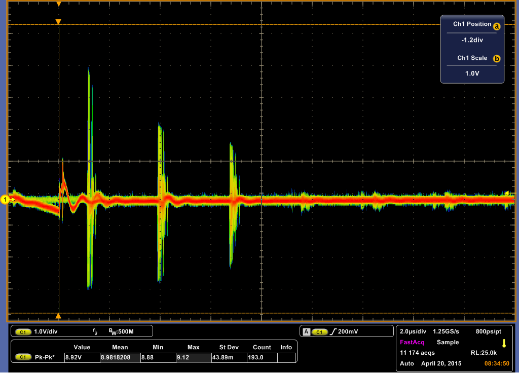
When we observe the input voltage we see some strange very high amplitude pulses on the devices that does not work properly. The device that draw less current does not show the spikes. The input capacitors are two PANASONIC 50SVPF68M devices with a low ESR (20mOhm), the output capacitors are four PANASONIC 6SVPE220MW devices with a low ESR (15mOhm) to.
The input voltage is 17 – 28V, the output voltage is 3,5V and is used to power some LED displays.
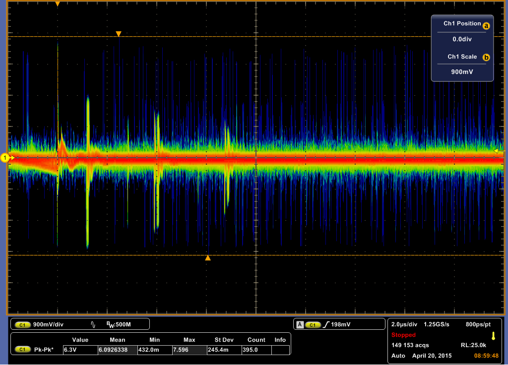
Attached two screenshots of my scope. The probe was connected directly to the pins of the module. I made two different measurements, with different loads (first less load than the second).
Meas 1 - ok:
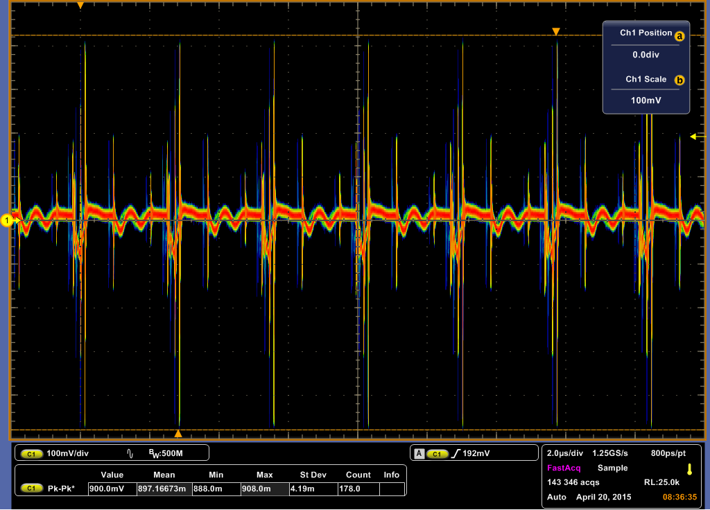
Meas 1 problem:
Meas 2 ok:
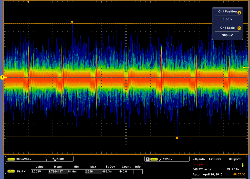
Meas 2 problem:
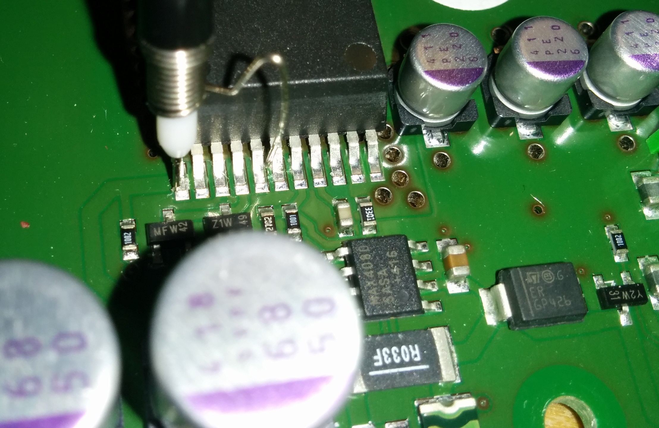
Probe connection, direct to module: