Because of the Thanksgiving holiday in the U.S., TI E2E™ design support forum responses may be delayed from November 25 through December 2. Thank you for your patience.

This thread has been locked.

If you have a related question, please click the "Ask a related question" button in the top right corner. The newly created question will be automatically linked to this question.

SG3524 External Synchronising

Other Parts Discussed in Thread: SG3524

Hi there

                I have about 10 SG3524N in my cabinet. I am setting up a controller that requires that I run parallel SG3524 together. My problem is that the Pin 3 designated as oscillator out gives only 200millivolts out. On some of the chips I have tested give even less than this voltage. As I am expecting to be looking for 3.5volts to tie these chips together should I be looking for a special coded chi? Or has this function been disabled on chips these days and the product datasheets are out of date?

Thanks

  • Hello Robert,

    The device datasheet is up to date and the device you have should have an OSC output as you are expecting of 3.5V from Section 7.6.

    What is your setup for testing this device? Do you have a scope shot of the OSC output?

    Best,
    Michael

  • Hi Michael,

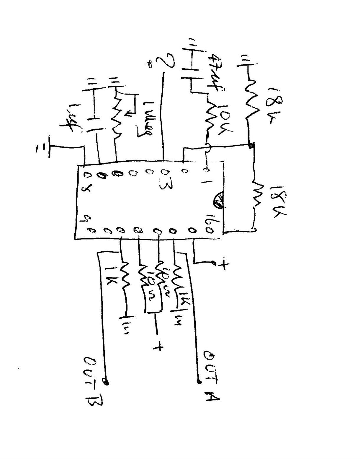
                        Thank you for your reply to my inquiry. I am uploading an image of my test circuit which I have copied to a doc file for uploading. It is a simple circuit. I am running this a low frequency. The output from pin 3 is essentially zero. Hope you can read my scribble!

    I am hoping that you can see the doc file I have pasted because I cannot see it my end as being inserted. Is there another method to upload images?

    Regards

    Robert   

  • Hello Robert,

    Unfortunately I can't see your document. If you are replying directly to my post then I suggest hitting the "Use Rich Formatting" at the bottom right.

    If you do this then it should bring you to a page where you should be able to more easily attach items by clicking the typical paper clip in order to insert a file.

    Please let me know if you continue to have trouble attaching and I am sure I can help work something out.

    Best,
    Michael

  • 3524 Osc Test.pdfHi there Michael,

                                      Here goes again. This circuit is just to prove the oscillator output. I have sent two files. The pdf looks a bit strange!

    Regards

    Robert

  • Hello Robert,

    One concern I have is your timing capacitor, and potentially the resistor based on the potentiometer setting.

    Our recommendations for these components are in table 7.3 from the datasheet.

    Best,
    Michael

  • Hi there Michael,

                                   It is possible to run the sg3524 at under 1Hz. At 0.5Hz it starts to get a bit flakey! Pulses can become a bit intermittent. However, I have been using the 3524 for a few years now at very low frequencies without any obvious issues. At the moment, I am looking to drive a series of relays that need to be activated on and off within the pulse cycle  whilst still being synchronised to the initial pulse leading edge.

    I have tried the parameters you have sent, and I still get no oscillator output. As the schematic indicates a direct pathway to the oscillator out pin from the oscillator I cannot see why I am not getting an output. At the RT CT 100K and .1uf no osc out.

    I am now setting up a series of 555 timers driven by 3524 as the sychronising source. I would have preferred the parallel 3524's, but, I need to get some proof from the circuit I am developing.

    Thank you for your assistance regards

    Robert

  • Robert,

    The data sheet maximum range for RT makes sense because at some point the current source mirror won't provide enough current for the CT voltage comparator in the oscillator. For low frequency adding to CT may be better.

    At 0.1uF and 100k, the oscillator should be running. What signal is on the CT pin (10M ohm probe or higher)?


  • Hi there Ron,

                            Thanks for the reply. I have previously had up t0 2uf on the CT pin and have found that for my present  application the 1uf gives more stable switching. The scope output on pin 7 is reading a peak between 3.5 - 4 volts.

    Thank you

    Robert

  • Robert,

    I will check the CT pin and oscillator output in the lab next week.
  • Hi there Ronald,

                                  My internet connection has been down for the past five days. In the meantime I purchased a couple on new SG3524 chips. These are working and at the low frequency that I wish to work at I am able to modulate the relays as I wish. I am thinking that the old chips must be a bad batch. Cannot recall where I bought them. Anyway, all good, and thank you for your assistance.

    Regards

    Robert

  • Robert,

    Glad you were able to figure it out. Always happy to help.

    Best,
    Michael