Because of the holidays, TI E2E™ design support forum responses will be delayed from Dec. 25 through Jan. 2. Thank you for your patience.

This thread has been locked.

If you have a related question, please click the "Ask a related question" button in the top right corner. The newly created question will be automatically linked to this question.

BQ24295 effects of reverse currents

Other Parts Discussed in Thread: BQ24295, TPS25942A, BQ24195

Hi

For the BQ24295, if a reverse current of ~400mA at 5V comes into PMID and SYS, will the chip fry? I see that BATFET can be turned off via I2C to disconnect the battery, but could the current harm other circuitry? The absolute maximum for PMID and SYS is 15V and 6V, respectively, so I wonder if a current coming in reverse could cause damage.

Thanks

John

  • Hi John,

    Please give more detail on what is the issue. What exactly is the situation? Are you saying what would happen if we input power through PMID and SYS? Is it that VBUS is drawing current instead of supplying?

    Both PMID and SYS are used as output power, not input. BAT can be used as input/output power, depending on whether it is charging or supplying. VBUS is input power only.

    Thanks,
    Steven
  • Hi

    Sorry, what I meant is that if I have a second 5V power source in the circuit, and suppose only one power source can be switched on at a time, would the BQ24295 be damaged when switched off? That is, would the current enter in reverse from PMID/SYS into ground damaging the circuitry?


    Thanks
    John

  • Hi John,

    PMID will not get damaged with current going in or out.

    I can't find a situation where SYS would have current going into the device, unless a power source is in SYS. In any case if there is an alternative power source, it should be the battery connected at BAT.

    Small transient times with -400mA shouldn't matter. There must be something connected wrong if SYS has -400mA constant current, as SYS should be a load and not a source.

    Thanks,
    Steven
  • Hello Steven,

    Why is it that no damage will be caused even with current going into PMID from the second power source? Are the body diodes of the FETs capable of blocking 400 - 500mA at 5V?

    If SYS is hooked up to the system and a second 5V power source is also hooked up to the system, the second source could be in parallel with the BQ24895 setup. Because the second source is 5V and BAT can not take 5V, it is connected straight to SYS. It's also connected to PMID in order to power the USB device OTG. In that case, there is a chance for the current to go in from the second source into the chip through SYS (and PMID for that matter) - correct? If so, could the reverse current cause damage?

    Thanks
    John
  • Hi John,

    PMID can be used to input power, but the converter will not turn on unless there is voltage at VBUS. The bad thing about input power through PMID is that you have no input current limit feature which controls this power source. Input current limit only takes into account the current from VBUS. The body diodes will not let current pass.

    Can I see a schematic?

    Thanks,
    Steven
  • Hi Steven

    I'm aware that the converter will not switch on, but I just wonder if the current coming in from the alternative 5V source will damage the chip in some way.

    I've reduced it to a simplified diagram

    Thanks

    John

  • Hi John,

    If you want to turn on the alternative source, you first disable 5V at VBUS. What you can do is put a low Rdson power MOSFET at PMID and another at SYS, which are driven by a control FET connected to VBUS with a voltage divider 100k/100k or any combination you may want to use, that way when the 5V at VBUS turns off, it will isolate PMID and SYS from the alternative 5V source, it will block current going into these pins and any possible damage can be prevented. Make sure that the isolation occurs before turning on the alternative source.

    Thanks,
    Steven

  • Hi Steven,

    Yes, VBUS will be disabled. I did contemplate of having MOSFETS or Schottky diodes, but I wonder if PMID and SYS are already isolated by design? That is, even without the MOSFETS or Schottky, the isolation of either or both pins could still occur. If they're already isolated (when VBUS is turned off), extra circuitry for isolating PMID and SYS will be redundant.

    For instance, don't RBFET and HSFET isolate PMID? Or could they themselves be damaged?


    Thanks
    John

  • Hi John,

    Yes, PMID is already isolated, but say if OTG is enabled, then PMID is no longer isolated. SYS is not isolated. I am worried this solution will not work even though in theory it seems to work. There are alternatives which we can think of.

    There might be a better way to solve this. I need to know exactly what is your end application. What is the requirement of the system (voltage range)? What is the logic behind having two power sources? Instead, why not put both power sources at VBUS controlled by a MUX?

    Thanks,
    Steven

  • I've sorted it out now. Thanks.

  • Hi John,

    When VBUS is active, you can have voltage and current at PMID, the voltage at PMID with VBUS active is: V(PMID) = V(VBUS) - Rdson (Q1) * I(VBUS). However, this current at PMID will reduce the current available to SYS and BAT.

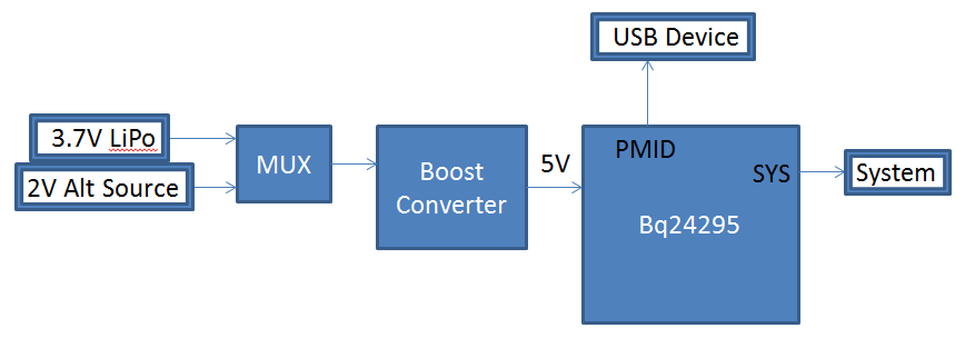
    The LiPo will have to be boosted to a constant voltage (like 5V) so that VINPDM doesn't get triggered once the battery starts depleting. Also, the minimum input for bq24295 is 3.9V. The bq24295 is capable of 3A max input current. Make sure that the battery does not exceed rated max constant amp output: IBAT = 3A * 5V * 1.1 (assumed 90% boost efficiency) / VBAT

    The 2V 500mA source boosted to 5V will provide 180mA at input assuming 90% boosting efficiency.

    I suggest looking into this application note: www.ti.com/.../slva715.pdf
    It explains how to use the TPS25942A as a power MUX for multiple input sources, and has reverse current blocking protection which makes it a safer system.
    To simplify your design process, you can also use www.ti.com/.../slvc571 calculation tool.

    Thanks,
    Steven

  • Hi John,

    This diagram should simplify what I think your design should look like:

    Thanks,

    Steven

  • Hi Steven,

    Thanks for that. I wonder if a MUX could be avoided. For instance, how about the following circuitry?

    The idea here is to block current from going into SYS and PMID when the alternative input is in place. I believe you briefly mentioned in an earlier post the impossibility of using MOSFETs to protect PMID and SYS - is that right?

    Thanks

    John

  • Hi John,

    Yes, MOSFETs can block reverse currents, but something more will create a problem: What happens when VBUS is on/ alternative is off and both PMID / SYS have different voltages? They both seem to be connected to the same node on your design, which is not good when both are regulated at different voltages by the bq24195. Just using reverse blocking FETs will not be sufficient.

    Please draw a complete diagram of the whole design, including the 3.7V LiPo battery, connections to VBUS, SYS, BAT, PMID and also the connections on the 2V alternative source. Draw it in paper or computer graphics, whichever is more convenient for you. This will greatly help in finding the correct solution to this problem.

    However, I still highly suggest just using a MUX at VBUS. The design is cleaner and safer from any damages that may happen. Just let the bq24195 power up the USB Device/ System and only control the MUX based on which input source is connected.

    Thanks,
    Steven