This thread has been locked.

If you have a related question, please click the "Ask a related question" button in the top right corner. The newly created question will be automatically linked to this question.

TPS2112 - datasheet clarification

Other Parts Discussed in Thread: TPS2112, TPS2112A

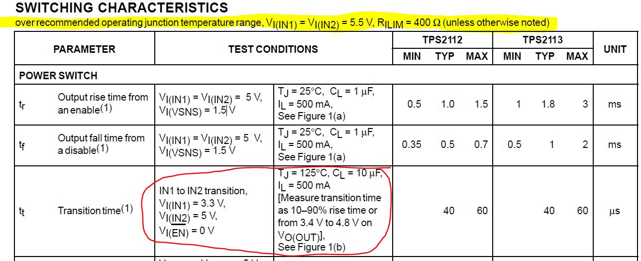
Good day. Datasheet for TPS2112 have "transition time" specification (marked as "Tt"). The questions are:

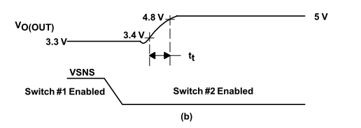
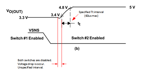
1. Does that transition time already include worst case switchover delay during the IN1 to IN2 transition? In accordance with Figure 1b - it is not (since only rise time marked), but common sense dictate that switchover delay inside this specification. 

2. If answer to question #1 is "Yes, worst case switchover delay is inside transition time parameter", next question: is that correct to have holdup capacitor designed for 60us max ? Or it can be reduced, since the actual switchover time is just a part of specified Tt = 60us ? 

  • Hi Dimitry,

    This part falls under the Power Interface forum.  I will go ahead and move this post there.

    Thanks,

    Alek Kaknevicius

  • The Tt parameter in the electrical characteristics section is measured and guaranteed under the following conditions:

    Does this help?

  • Hello Eric! That is exactly what I've been tried to clarify. Look at the bottom note "See Figure 1(b)". Here is Figure 1b:

    As we can see from Figure 1b, Tt marked as rise time during IN1 to IN2 switching. This slow rise time help to minimize inrush current, that is ok. But before transition IN1 to IN2 will actually happen, a short interval when both switches are disabled will occur. Here is that time interval:

    So, according to Figure 1b,  this interval is not inside Tt. It is separate time interval. And therefore it's worst case not specified, only typical values can be calculated from the Figure 5. During this "dead time" interval, the output voltage drops out, so we need hold up capacitor to prevent excessive drop out. The worst case value of capacitance depends on worst case "dead time" interval, when both switches are off. So, the question is the Figure 1b wrong or "dead time" intentionally unspecified ?


  • Hi Dmitry,

    Thank you for the clarifying graphic and now I see your point. My understanding is that figure 1b is correct and that the dead time is not specified or bounded.

    I might point out that there is an "A" family (TPS2112A for example) where this droop is reduced (by 75% in some cases as shown in the TPS2112A DS, figure 6).