This thread has been locked.

If you have a related question, please click the "Ask a related question" button in the top right corner. The newly created question will be automatically linked to this question.

About voltage feedback circuit of UC3527A

Guru 19555 points
Other Parts Discussed in Thread: UC3527A

Please let me know about feedback of UC3527A.

(Please see below)

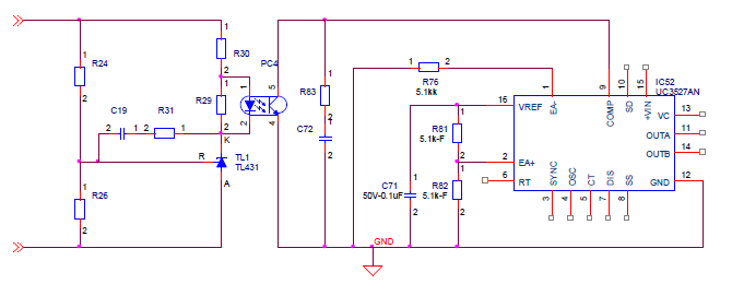
①Is attached circuit no problem? (Unused internal error AMP)

②If no problem, is there spec of error AMP's current limit?

   ※Customer want to know threshold of PWM comp<0.7V (zero duty cycle)

③Is there application note or reference circuit of Voltage feedback?

Best regards,

Satoshi

  • This is an acceptable method of feedback control for the UC3527A when used with an optocoupler.
    The UC3527A uses a trans conductance type amplifier which acts like a voltage controlled current source.
    The data sheet on page 5 shows that it can source 100uA.
    PWM is generated by comparing the COMP signal with the CT (or ramp) signal.
    The amplitude of the ramp is specified as 3.5v (typical) but its minimum value is not characterized in the data sheet.
    Therefore 0.7V is probably a good value for zero duty cycle.