This thread has been locked.

If you have a related question, please click the "Ask a related question" button in the top right corner. The newly created question will be automatically linked to this question.

Limit Vbuck in LM3444 Circuit to less than 150VDC when connected to US Mains 120VAC power input

Other Parts Discussed in Thread: LM3444

Hello,

I have an LED component in which the input is limited to a maximum of 150 V DC from + to earth Ground per UL, but be greater than 50 V in order to operate. The voltage drop across the LED itself will be on the order of 40 V.  Looking at the example circuit for the LM3444, if we were connected to 120 V, 60 Hz mains input, then the peak voltage at Vbuck could be around 170 V and if assuming a worst case of 135 VAC, the Vpeak could be 190 V.  In both of these scenarios, the Vbuck would violate the 150 VDC maximum from the + side of the LED to earth ground (heat sink in this case or housing of the LED).  What are my options for limiting the Vbuck voltage to below 150 VDC?

The current passing through the LED will be 2.5 to 3.0 Amps and the voltage drop across the LED is 40 VDC.

Is the only option available, to use a transformer at the mains input or can I use some sort of Zener diode circuit to help clamp the Vbuck value to below 150 VDC?

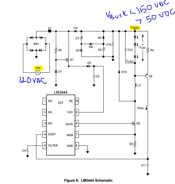
See the attached image for reference.

  • Hello Brandon,

    Before I start.  The ground symbol on the LM3444 is not earth ground.  The LEDs are driven between the + and - rails which are not tied to earth ground.  The (+) rail will have peak voltages of 170 volts every half cycle and the (-) will have peak voltages of -170 volts every half cycle.

    I'm not sure where your 150 VDC voltage rating to earth comes from.  Note that the peak voltage to earth will be about 170 volts.  You would have to check with UL but I don't believe they use line tolerance for safety.

    This is also a non-isolated design so that may also change how UL looks at this, again you would have to discuss this with UL.  It will require creepage and clearance to the circuitry, again UL specified.  The schematic you attached is a valley fill so the LED current at a 40 volt stack will be continuous (if the electrolytic capacitors are large enough).  At 120 VAC input the DC level will be about 84 volts discharging at the current draw rate (i = C dv/dt) during the time the rectified AC is below 84 volts (I'm neglecting diode drops).  The two capacitors at this time are in parallel, they charge in series.  At 90 VAC input the DC level drops to about 63 volts.

    You cannot clamp the input voltage to 150 volts, current would only be limited by the impedance of the source and circuit board/components.  You can add series drop but at a huge power loss (excess heat to deal with and not realistic).

    Thanks,