Hello,
My customer is having problems with the part BQ29700DSET protecting Panasonic NCR18650B:
http://www.digikey.com/product-detail/en/texas-instruments/BQ29700DSET/296-37746-1-ND/4840671
http://www.batteryspace.com/prod-specs/NCR18650B.pdf
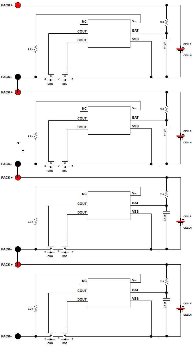
In their application, there are up to 4 cells in series as shown in the attached, on a PCB. There are two differences between TI's datasheet schematic and their application:
1) use of IRLR3110 N-MOS parts instead of CSD16406, chosen for the fab technology and the Rds:
http://www.digikey.com/product-detail/en/texas-instruments/CSD16406Q3/296-24251-1-ND/2038321
2) Use of INA117 as shown on page 13 of the datasheet, directly across cell terminals
http://www.digikey.com/product-detail/en/texas-instruments/INA117KU-2K5/296-26055-1-ND/2254829
Most boards seem to work initially when they run the string through initial over-voltage, under-voltage, and short-circuit tests, but several have failed after working for some time. A few circuits have failed such that Vbat and Vss are shorted or reduced to ~30-Ohm resistance, so that the cell begins to drain through the 330-Ohm resistor. On other failed circuits they’ve measured out-of-spec pull-up resistance between V- and VBAT, either too low or too high. On many of the failed circuits, it looks like the chip is stuck in an over-current protection mode, because there is ~Vcell from source-to-source of the MOSFETs, however shorting the sources together doesn’t reset the chip. Usually, failed circuits won’t charge but may discharge.
They have a few of the EVMs for the BQ29700DSET part on hand, and they've hooked them up in series and thoroughly tested the string terminals for under-voltage, over-voltage, and short-circuit without any failure. They like to know if there are some specific measurements that would be helpful and they are suspicious that the FETs are causing problems. Please advise.
Thanks,
Mehrdad.