This thread has been locked.

If you have a related question, please click the "Ask a related question" button in the top right corner. The newly created question will be automatically linked to this question.

TPS68470 application

Other Parts Discussed in Thread: TPS68470

Hi,

The question is summarized as below.


  1. First of all, Intel does not support customer to configure TPS68470 registers as they want, so customer can only consider HW change to fit their need.

  2. Intel would not enable both ILEDA and ILEDB simultaneously.

  3. ILEDA current is fixed at 16mA based on our chip design.

  4. ILEDB current is configured as 2mA when it’s enabled based on Intel’s SW  driver.

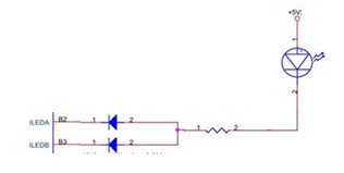
  5. As the schematics below, customer's purpose is to keep the LED current as 2mA when ILEDA is enabled in TPS68470.  Customer considers to add resistor to keep LED current as 2mA.  Do you think it’s feasible?  How should they choose the value of this resistor?  (LED spec is http://www.fairchip.com/pdf/Everlight/19-217-T1D-AP1Q2QY-3T.pdf .)

Antony

  • Antony,

    1. Customers of-course have the ability to change the HW configuration of the PMIC. Many don't use the wLEDs or the boost and sometimes people use it with just one camera. Whether Intel will support them that depends on the change and is a question that should be ask of your local Intel rep.
    5. I think this is risky as the Vf dropout must be considered here and analyzed at the minimum Vin of the 5V rail. That rail could drop down to 4.5V for example on a transient or something. The wLED may need up to 3.2V for Vf leaving only 1.3V for the indicator LED which would not be enough to turn it on.

    Why do they want to do such a configuration? I might be able to provide an alternative if I understand what is the goal here.
  • Hi Michael,

    What is the minimum voltage for ILEDA and ILEDB for normal operation?  From your reply, do you mean 1.3V is too low for these two pins?

    THanks!

    Antony

  • Antony,

    I don't think the part will pull ILEDA/B to a negative voltage and thus, bottom out at 0V. This means that for the entire string there is 5V potential. The 5V will vary as any regulator will especially during transients so, we must use the minimum voltage on the 5V input,... estimating about 4.5V. The wLED would have a drop out of up to 3.2V leaving only 1.3V for the resistor and iLEDs. iLEDs would likely need more Vf than 1.3V to turn on thus, the whole string would not turn on in certain cases.

    My recommendation is to first find a wLED that is meant for few mA of operation to match the application. Then remove the iLEDs from the string to give the string enough voltage drop to supply the wLED. You can build a a simple iLED driver with the enable condition of ILEDA/B going low indicating string is on.
  • Hi Michael,

    Can you provide more detials about "You can build a a simple iLED driver with the enable condition of ILEDA/B going low indicating string is on."?  I don't fully understand this.

    If it involves any PMIC register access, unfortunately it's not workable for Asus.  Intel does not support customer to do any register configuration additional to the original SW driver from Intel.  I understand it's the issue between Intel and the customer, but that's why customer comes to us for help,

    Thanks!

    Antony

  • Hi Antony,

    In addition to the above question, customer has another concern as below.  May I have your comments as well?

    • Consider ILEDA is configured as 16mA in PMIC register, would it cause any issue if we limit the current to a lower level through the resistoer in series?

    THanks!

    Anotny