This thread has been locked.

If you have a related question, please click the "Ask a related question" button in the top right corner. The newly created question will be automatically linked to this question.

Problems with tps28226

Other Parts Discussed in Thread: TPS28226

Hi!
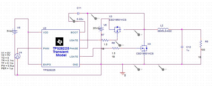
I have the circuit of the image mounted on PCB but using tps28226(And using 6.5 V as a source for the driver), there are no problems with the devices or continuity. The driver is working fine when is not connected to the rest of the circuit, but when i connect the mosfets, the drivers stops working fine and in some point it gets hot and a short circuit appears between LGATE and GND.

I've been trying everything, but there are no problems with other devices or the PCB
What can be happening?

  • Hi Alejandro,

    I have asked on of our applications engineers to help with this application.

    Regards

    Peter
  • Hello Alejandro,

    We regret you are having some issues with the application with the TPS28226; there are some suggestions to address potential issues that occur in some applications.

    Confirm there is not high frequency noise or ringing on the PWM pin to ground with the scope probe connected as close as possible to the IC pins, and other scope probe ground not connected in any other locations.

    High voltage spikes on the gate drive pins above VDD and below ground has the potential to cause issues with the driver, if there is enough energy during the voltage spikes. Long PCB layout  paths from the driver gate to MOSFET gate, and MOSFET source to driver GND (or PHASE for high side) can cause large voltage spikes due to the parasitic inductance of the PWB traces. As an experiment to see if this is the issue; the driver output can be clamped to ground with a schottky diode connected to the LGATE and GND, and UGATE and PHASE. Voltage spikes above VDD can be clamped with schottky diodes from LGATE and VDD, and UGATE and BOOT.