


I have a question regarding the design of an application with TLC5940 chips.
Main question
When designing LED applications with TLC5940 drivers (with seperate LED supply and VCC for the TLC); would one use capacitors at the anode side/supply side of the LEDs? And if so, for what purpose would one place these capacitors? And what value, how many and where? (Maybe smaller ones close to each LED, or bigger ones spread across the board, at a certain interval? Or maybe just add capacitance close to the power supply?)
Let me now explain my application to give you some context.
My application
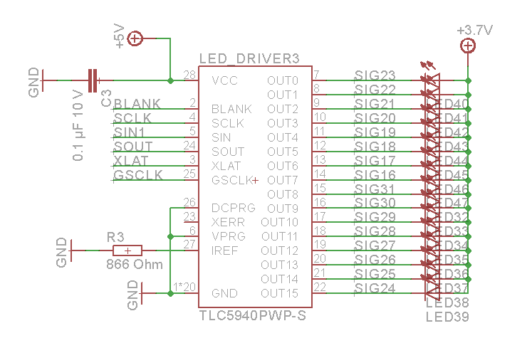
Basically I have created a setup of two parallel custom LED strips of each 128 LEDs, that are controlled by 8 TLC5940 LED drivers. The complete setup with the two LED strips then have 2 * 128 = 256 LEDs in total, and are thus controlled by 16 TLC's. The system is powered and controlled from one side, so there are extra controller and power supply boards on this side. On the custom LED boards, the TLC's are powered separately from the LEDs; the TLC's are powered with a 5 V rail, while the LEDs are powered by a 3,7 V rail. They do share the same common ground. The TLC chips are decoupled with 0,1 uF capacitors at their 5 V supply, close to the IC. The LEDs I'm using are LUXEON 3014 LED's that have a forward voltage of around 3.1 V and the TLC's are configured to source 45 mA per LED. Due to the TLC driver setup, I can control each LED separately, so the current draw of the system varies between 0 and 0,045 * 256 = 11,5 A. The 3,7 V power supply is generated by a DC-DC converter that transforms 12 V DC to 3.7 V. The schematic of how each TLC5940 is connected is rather standard:
What I've looked into
I have checked several sources to try to answer this question. I have looked at example schematics around the internet, and I have looked at the SLVA242 application report (July 2006) by TLC, titled LED Display System Module Using Cascading TLC5940 Devices.
In this report a typical application schematic is given, where no capacitors are shown on the V (LED) supply:

In a more elaborated example, capacitors are drawn, but I'm not sure where they would be positioned in a PCB design of this schematic. Refer to the red circles in these screenshots. The following description is given next to the schematic:
"TLC5940 Reference Design
This EVM contains three TLC5940 ICs that are connected in series. The three TLC5940 ICs drive 16 red-green-blue light emitting diodes (RGB LEDs). Each TLC5940 drives a separate color. Each TLC5940 has 16 outputs and each output is connected to a different LED. Using the software, the user individually controls the DOT correction and grayscale values for each color of each LED. The following reference design contains three TLC5490 ICs that are connected in series. The three TLC5490 ICs drive 16 red-green-blue light-emitting diodes (RGB LEDs). Each TLC5490 drives a separate color and has 16 outputs and is connected to a different LED."
This is the elaborated schematic given in the application report:
In applications by people on the internet I have found several examples of setups where no capacitors are used at the supply side of the LEDs. But on others I did find them.
Any help is welcome. Thank you in advance.

