This thread has been locked.

If you have a related question, please click the "Ask a related question" button in the top right corner. The newly created question will be automatically linked to this question.

BQ769300 issues

Other Parts Discussed in Thread: BQ76930, BQ78350-R1

Hello,

I'm a university student trying to build a BMS using the BQ76930 AFE and the BQ78350-R1 Fuel Gauge. I built it based on the EVM schematic and recently started to test. Hint: It's not working!

**Problem**

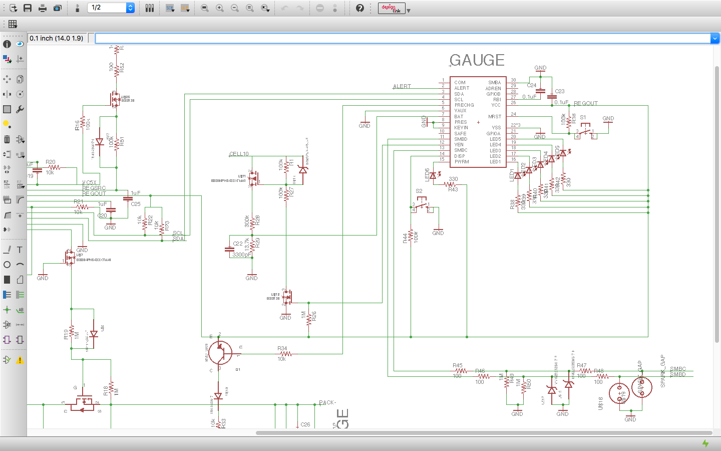
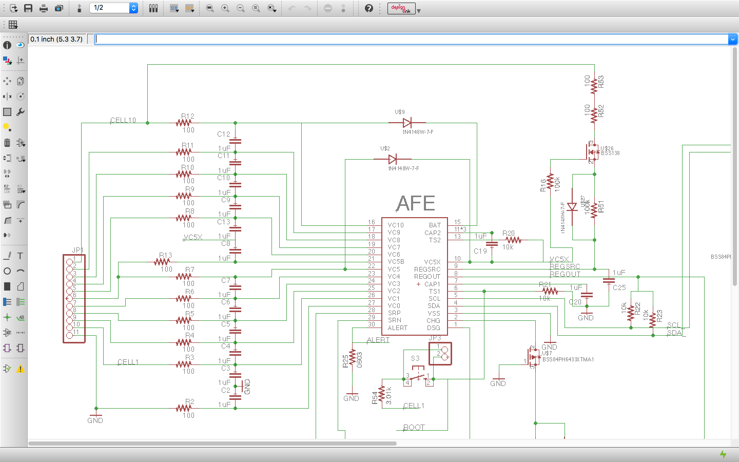
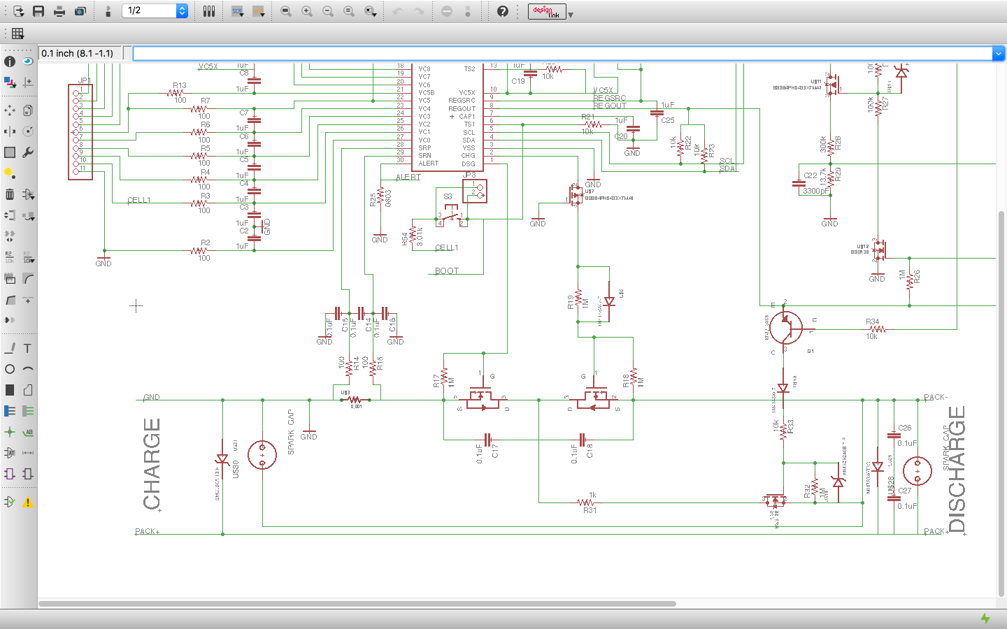
When I hit boot, it looks like the source follower FET (BSS138) gets very hot and the BQ76930 heats up as well. I can't seem to figure out what is wrong, and after double checking it doesn't look like I have shorted anything. Note that I have also tried bypassing the FET and applied voltage at the SRC as well, just in case it was only a FET sizing problem. The FET was obviously off, but the BQ AFE was still heating up. 

If you find any other issues, I would be very appreciative. I'm pretty new at all of this.

Question: If I wound up only using only AFE would there be any good way to check for a low battery? It doesn't have to be exact either, just a general *charge this soon*. I suppose maybe getting the cell voltages might give a general idea? 

I would like to hear that the chip is bad and I should just replace it and it would work but I'm pretty sure there is some type of user error here. Any help would be appreciated!

I posted EAGLE brd/sch files, apologies I'm not using anything more robust/common to industry.


**Measured Values**

The battery pack is currently sitting at 40.5V (10s Lipo 5000mAh)

At rest:

CELL10: 41V
CELL9: 36.8V
CELL8: 32.7V
CELL7: 28.5V
CELL6: 24.4V
CELL5: 20.5Vx2
CELL4: 16.5V
CELL3: 12.6V
CELL2: 8.4V
CELL1: 4.21V
CELL0: 92mV

BAT - 40.6
CAP2- 20.1V
TS2 - 20.1V
V5X - 20.1V
REGSRC - 19.6V
REGOUT - 0V
CAP1 - 0V
SCL/SDA - 0V

Source Follower
(BQ OFF):
G = 20V, D = 40.9V, S = 19.7V

(BQ BOOT):
G = 19.8V, D = 32V, S = 19.6V,

Off (100ohm, Drain):  Resistor Voltage = 84mV,
Boot-On: Resistor Voltage = 3.92V

Current from Source Follower = 3.92/100 = ~40mA. This seems way too high. Tested that both the BQ and the FET are getting hot. 

**Schematics**


10S.brd

10S.sch

  • Hi Charles,
    40 mA is too high for input to REGSRC or output from REGOUT. You might use common diagnostic techniques to find where the current is going. On new builds be sure to check for unexpected shorts or wrong components. Much like the FET analysis you may need to lift the leads of REGOUT and/or REGSRC to determine if the current is in the part or on the net. Sometimes you may need to lift the part or IC to check for contamination under it, at that point you might just try a new part.
    Some observations:
    I don't immediately see the CL capacitor on REGOUT, 4.7 uF is typical. A minimum 1uF is recommended, C23 is likely a long way away from the REGOUT pin and too small to serve this need (C23 is for the gauge power). You might try adding a bulk cap near the AFE.
    On the AFE pins 11, 12 and 14 should all be connected to the C19 capacitor, you may have that since I did not look at the layout but I'm not familiar with the designation on the schematic. I don't think this would affect REGSRC current unless there is some extra unexpected connection.
    I don't see the power filter Rf and Cf for the BAT and VC5X pins. The 1k and 10 uF values from the are common for a bq76930. I would not expect these to influence the REGSRC current, but you will need them for proper operation.
    The 100 ohm Rc input filter resistors are rather small for a bq76930 design, 1k is more typical. Once the board works be sure power stays above Vshut level during short circuit. Related to Rc the Cc may need to decrease with the larger Rc so the filter settles fast enough during balancing to avoid measurement artifacts.

    Hope this helps.
  • the d/s does not have max spec for REOUT. Use 20mA has max.

    on the REGSRC, be mindful of the operational range of  6V-25V.  In our literature, we recommend operation ~ 12-13V. Hence, on the source follower configuration,

    try to drop the  voltage on the drain side of the FET. Use ~ 1K. So with 20mA current to be sourced from the top of the stack, Vgs of the FET can be around 20V under normal operation.

    Also when the cell goes to 2V/cell, adhere to the following equation and not to violate the below equation.

    Vregsrc (min) = VC5X-( Vgate_fet) - (Vgs_fet)- (Vdiode)-(Vr_src)….=6V.

    On the ALERT pin, use ~ 500K || 500pF to give a time constant of 250uS.

    on the bq76930/40, please note the internal balance current (Icb) =5ma.  Hence the of  Rc ~ 1K, Cc

    V =  4V= ( 2* Rc + Rds-fet) I(cb);    with   Rc =1K, Rds_fet ~5 ohm     Icb = 4V/1Kohm , Icb = 4mA 

  • Thanks,
    I took another look at the circuit and tracked down the short to the BQ78350-R1. I double checked all the pins but the circuit shorts out when the chip is soldered (I tested with it removed).

    Do you think it might be a defective chip??
  • Thanks Vish,

    I had forgotten about replacing Rf with the 1k for proper balancing current.

    What value for Cf would you suggest? The BQ76930 EVM Schematic shows 1uF caps but WM5295, above mentioned 10uF. You're the deciding vote?
  • yes, please replace the iC. and also check the landing pads.
  • 1uF may work for the power filter caps Cf, but on the EVM refer to C34 and C35: CAP, CERM, 10uF, 35V, +/-10%, X7R, 1210. R58 and R59 are Rf, 1k. R61 and R62 are current measurement shunt resistors for the EVM, these are not needed in a design.
    The load on REGOUT may be too much if the gauge tries a flash update when all LEDs are on, be sure to check operation.