This thread has been locked.

If you have a related question, please click the "Ask a related question" button in the top right corner. The newly created question will be automatically linked to this question.

TPS68470: ILED and 3V3_SUS questions

Part Number: TPS68470

Hi,

Some questions as below.

  1. If LDO_AUX2 is not used, how should we connect 3V3_SUS?
  2. If 3V3_SUS is supplied before 3V3_VDD, is there any side effect?
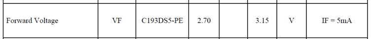
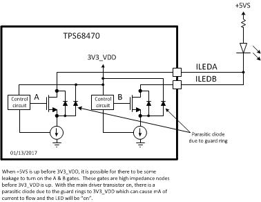
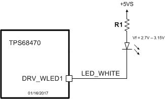
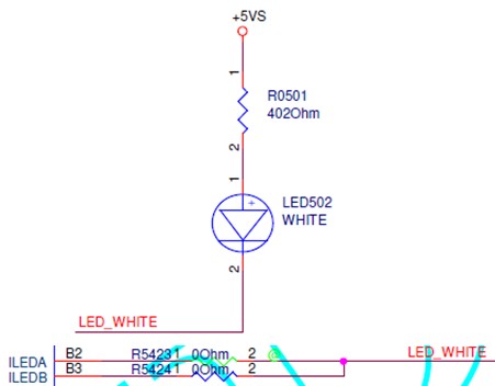
  3. As below, if 5VS is supplied while 3V3_SUS/3V3_VDD is not available yet, customer found the LED will be lighted up.  Is this normal?  Why?

Thanks!

Antony

  • The answers are numbered as follows:
    1. The TPS68470 has two power supply input pins, 3V3_SUS and 3V3_VDD. So the 3V3_SUS pin must be connected to a well-regulated 3.3 V supply as stated in specification section 10 Power Supply Recommendations.
    2. The TPS68470 only starts the internal power-up sequence when both 3V3_SUS and 3V3_VDD are above the Under voltage lockout threshold of nominal 2.75V as specified in specification section 7.5 Electrical Characteristics.
    3. There are ESD diodes on the ILEDA and ILEDB pins to the 3V3_VDD pin. Since the 3V3_VDD is not up, these ESD diodes are forward biased and they conduct and the LED will light up. This is not recommended operation since the ESD diodes are designed to carry a large amount of ESD current for a short duration. They are not designed to carry the current that is possible with this configuration for a long period of time. The recommended supply for the Indicator LEDs is the 3V3_VDD supply. The Absolute Maximum Ratings Voltage for the ILEDA and ILEDB pins is 3.96 V, as stated in specification section 7.1.
  • Hi David,

    Thanks for your reply.  Some more questions as below.

    1. Customer requests more details (e.g. An architecture diagram) regarding the LED indicator design within our chip in addition to the information in datasheet.  Is there anything we can provide?
    2. Customer use 5V to supply the LED because they're using the WLED as below which has a higher Vf.  Do you think we can support this WLED?  How should the schematics be for this WLED component?

    Thanks!

    Antony

  • Antony,

    I have a meeting set up with a designer tomorrow to research the answers to the customers questions. I apologize for the delay.

    David Street
  • Hi David,

    Thanks for your support. In parallel, customer has some more questions as below.

    1. If either 3V3_SUS or 3V3_VDD is not valid, all the functions of TPS68470 would not be workable, right?
    2. In some specific scenario when 3V3_SUS is supplied but 3V3_VDD is not valid, how much current consumption would it be?

    Thanks!

    Antony
  • Antony,
    For question 1 above: If either 3V3_SUS or 3V3_VDD are not above the under voltage lockout threshold, then all functions of the TPS68470 are not working.
    Question 2: The current consumption is specified in section 7.5 Electrical Characteristics: IQ(3V3_SUS) 3V3_SUS quiescent current [In SLEEP mode, VI(3V3_VDD)=0V, VI(3V3_SUS)=3.3V, LDO_AUX2 disabled and with no load] = 1.1 microAmps max.

    I am still researching the ILEDA & ILEDB driver details.

    David Street
  • Antony,

    Here is a conceptual drawing for the ILEDA & ILEDB drivers.  I misspoke calling the path an ESD diode but there is a parasitic diode from the source of the main transistor to the guard ring.  The guard rings are connected to 3V3_VDD.  The gates for the ILEDA & ILEDB main transistor are high impedance before 3V3_VDD is up.  These gates can charge up and turn on the main transistors and then there is the parasitic diode path from ILEDA & ILEDB to 3V3_VDD which is at a lower voltage and the LED will be "on".  Please see the following figure.

  • Antony,

    Here is my recommendation.  The DRV_WLED1 pin has an absolute maximum rating of 7.0 V.  The drivers for the WLED pins can handle up to 1 A of current.  The R1 resistor can be used to set the maximum current.