This thread has been locked.

If you have a related question, please click the "Ask a related question" button in the top right corner. The newly created question will be automatically linked to this question.

TPS68470: I2C waveform check

Part Number: TPS68470

Hi,

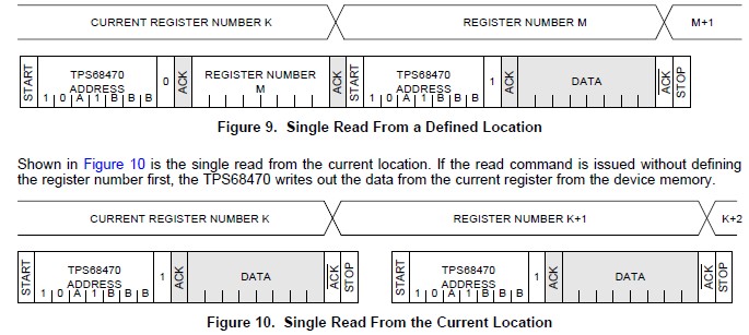
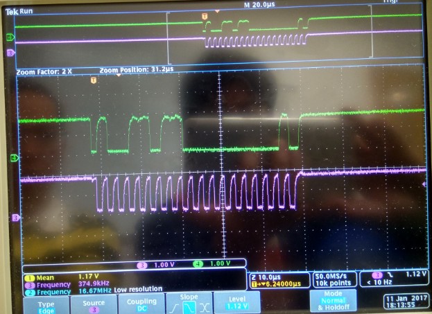
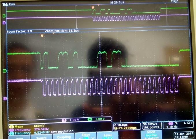
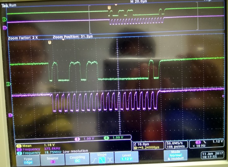
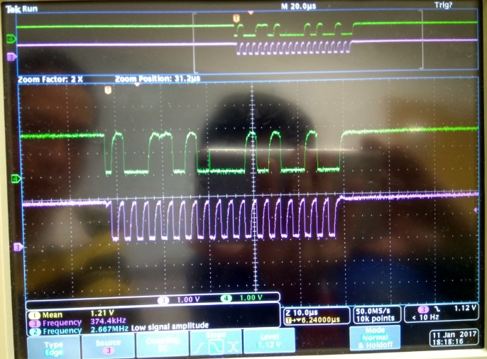
Customer is not sure if Intel implement SW driver correctly or not for I2C register access.  With both I2C_ICA and I2C_ICB connected to GND, they capture some I2C waveform plot as below.  From my point, I didn't see anything strange from TPS68470, but I'm not sure what the I2C master is trying to do here.  For example, the last waveform tried to write a register but it didn't finish.  Do you see anything strange from these waveform plot?

Thanks!

Antony

  • Hi Antony,

    I agree that waveform 4 did not complete the I2C write transmission for whatever reason. Also, from waveform 1 & 3 it appears there was an attempt to read but no acknowledge ever occurred following the device address so that is strange. The acknowledge should occur following the device address.  However, waveform 2 is the only one that makes sense. With I2C_ICA and I2C_ICB both grounded your sub-address for the TPS68470 is x9A for write and 0x9B for read. From waveform 2  it looks like they are attempting to write x00 to register x1B, that is  GPCTL3B for GPIO 3 control. Also, what resistor values are being used for pull-ups? It looks like they can improve the rise time.

    writing x00 to x1B result in:

    Trig=> edge sensitive

    Polarity=> Normal

    Hyst=> No hysteresis

  • Antony,

    Waveforms 1 & 3 seem to be identical. They are both reads to register 0x00 which is reserved and the TPS68470 responds with ACK=1 which causes the stop. I agree with Raymundo that the address for the TPS68470 is correct (0x9A for write and 0x9B for read) since the I2C_ICA and I2C_ICB are both grounded. I contend that waveform 2 is actually a write of 0x00 to register 0x36, the White LED control. Waveform 2 behaves correctly. Waveform 4 is a write to register 29 but for some reason, the master stops the transfer before sending the data byte. The TPS68470 acknowledges the receipt of the register byte before the stop is sent. I agree with your assessment on waveform 4.

    David Street
  • Thanks you are correct, 0x00 is being written to 0x36 the WLEDCTL register.

  • Hi,

    If I understood correctly, firrst waveform seem to be the case of Figure 10 shown below from the datasheet.  So, it seems TPS68470 behave correctly here.

    Do you see any concern about the rise time from the waveform plot?  I didn't have the full schemaitcs and can't see the value of pull-up resistor on I2C.  I'll check and let you know.  From the waveform plot, do you think they should increase or decrease the pull-up resistor value?

    Antony

  • Hi,

    The pull-up resistor value is 4.7kohm for your reference. Please let us know your comments.

    Thanks!

    Antony
  • Hi Anthony,

    You are correct, Figure 10 does reflect what is seen on waveform 1 & 3. No concern, I just noted that it looked like the waveforms were a bit rounded. From what I understanding this is typically due to the time constant, RC,  pull up resistance and the amount capacitance on the bus.  Using 4.7kohms seems just fine. Here is an app note to use as a reference when deciding on how large to make the pullup resistors.

    http://www.ti.com/lit/an/slva689/slva689.pdf

    -Ray