This thread has been locked.

If you have a related question, please click the "Ask a related question" button in the top right corner. The newly created question will be automatically linked to this question.

UCD9224: Startup Failure UCD9224E w/ UCD74120RVF

Part Number: UCD9224

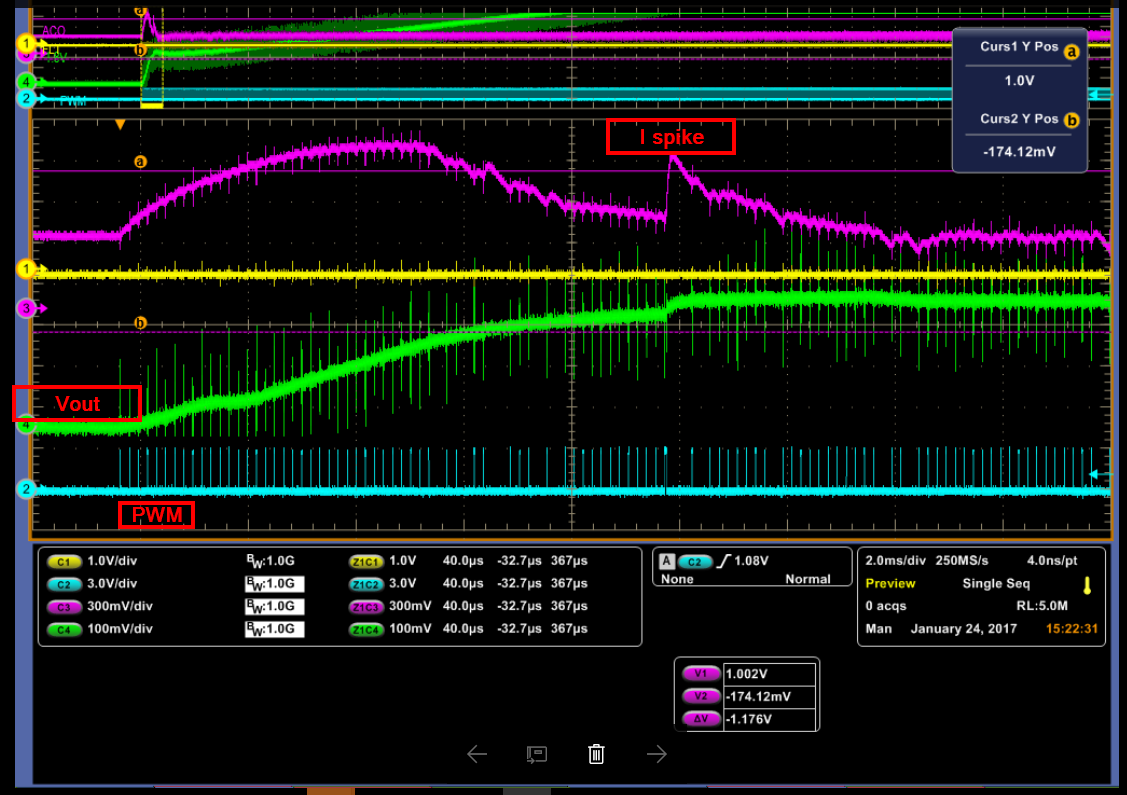
The scope picture shows a current spike (I spike) that happens after the kickstart period as the control system has just started doing closed loop control after the fixed PWM period.  The current spike is a direct result of the long PWM pulse.

This current spike does not cross the threshold, but similar current spikes often do and I don't want to rely on retries to patch the issue. The startup control system has adequate phase and gain margins. 

  • This spike at the transition between ramp and regulation can result from compensation values that are sufficiently different between the SoftStart and Regulation banks.

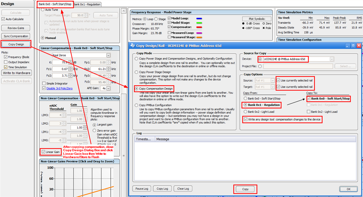
    I would suggest copying the Regulation banks settings to the SoftStart bank (as below) but click the Linear Gain checkbox (SoftStart/Stop bank) in the Non-linear Compensation setting, this is typically a stable setting with a lower crossover than the regulation setting.

    As the system is stepping the reference during the voltage ramp, it is artificially adding error, using linear gains during the ramp tends to provide a smoother ramp and the matching Linear Compensation values provides a smooth transition once regulation is reached.

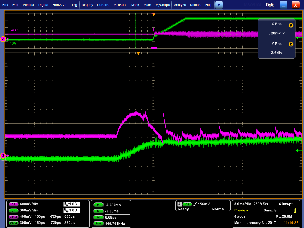
  • Thank you Brad.  I tried the suggested copy from the regulation to soft-start and selecting Linear Gain, but have similar current spikes on the ACO / IMON pin (same signal as original post).

    -Tom

  • Here are the two plots of measured loop response for startup and regulation.  The third one is taken after the startup compensation copy and linear gain checkbox change.

  • Here's the config file I'm using.   One more note: the current spikes that I see during the soft start happen at very regulatr 100 us intervals  (10KHz). 

    UCD9224E @ PMBus Address 65d Project_Retries-On_170124B.xml

  • What you are seeing now is of a completely different origin and is to be expected.

    There is a PMBus parameter called DRIVER_MIN_PULSE, which sets the minimum pulse width that the controller will output when first starting up a rail (there is often a suggested minimum on time for the driver at startup to unsure proper operation).

    You may notice that the softstart ramp may appear that it doesn't start where you would expect the rail would be enabled but does so slightly later in time.  The controller will calculate the amount of time from the enabling of the rail until the point on the expected softstart ramp where the DRIVER_MIN_PULSE would produce an output equal to the ramp voltage and then starts to output this minimum pulse width.

    The resulting system response is often referred to as kickstart, the voltage will initially rise up at a faster rate than the subsequent soft start voltage ramp.

    This kickstart will produce an inrush current and may occasionally produce a small secondary current spike as the control loop takes over from the open loop application of the DRIVER_MIN_PULSE and starts the softstart ramp to the regulation voltage.

  • The softstart ramp uses discrete steps at a 100us interval to ramp the voltage to regulation, you will see small current spikes at each transition.

    Here is an image I had captured previously from UCD documentation which shows an exaggerated example of a large DRIVER_MIN_PULSE setting.

  • Thanks Brad, yes, I just realized that myself, that the spikes are a direct result of the 10kHz DAC update frequency. The issue is that when the loop takes over, the first or second DAC update can produce a current that exceeds threshold set by the ILIM pin. Anything I can try to reduce these current spikes?
  • I'm not part of the support team for this part anymore but I can take a quick look at configuration.
  • Hi Thomas,

    What is the input voltage, output voltage, switching frequency, and current limit set by ILIM pin?

    Does the GUI Monitor page report input voltage correctly? 

    Thanks,

    Zhiyuan

  • Hi Zhiyuan, thanks for the response.

    Vin: 12V

    Vout: 1.8V

    Fsw: 300 kHz

    ILIM threshold: 14.1A

    Yes, the input voltage is reported correctly.

    In a previous response, I attached the full XML file as well.
  • Hi Thomas,

    If you increase Rise Time, the DAC update step will be smaller, and thus the current spike when DAC update will be smaller.

    Also, there are 3.3mF for this 6A rail. If you can reduce cap size to, say, 1mF, the current spike will also be significantly reduced.

    Thanks,

    Zhiyuan

  • Hi Thomas,
    If you increase Rise Time, the DAC step will be smaller, and thus the current spike when DAC updates will be smaller.
    Also, there are 3.3mF for this 6A rail. If you can reduce cap size to, say, 1mF, and adjust compensator accordingly, the current spike will also be significantly reduced.
    Thanks,
    Zhiyuan
  • OK, thank you for the suggestions Zhiyuan. -Tom
  • HI Zhiyuan,

    I was looking for a review of the loop response that I posted on Jan 31, can you take a look?

    Thanks

    Tom