This thread has been locked.

If you have a related question, please click the "Ask a related question" button in the top right corner. The newly created question will be automatically linked to this question.

UCC28510: It does not start PWM by flyback converter

Part Number: UCC28510

Hi!
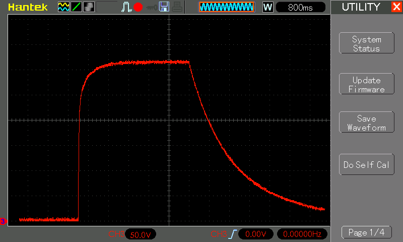
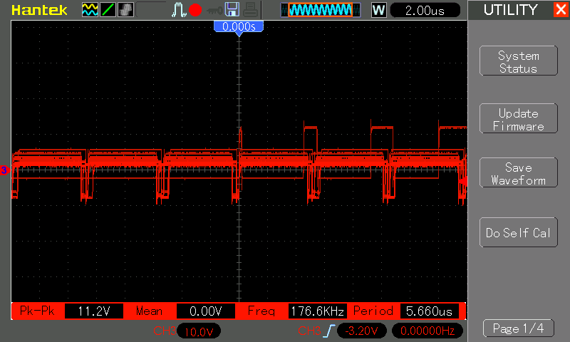
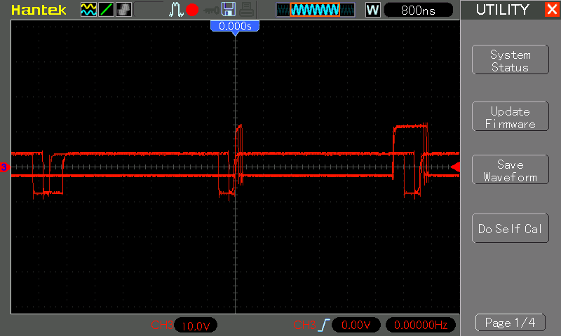
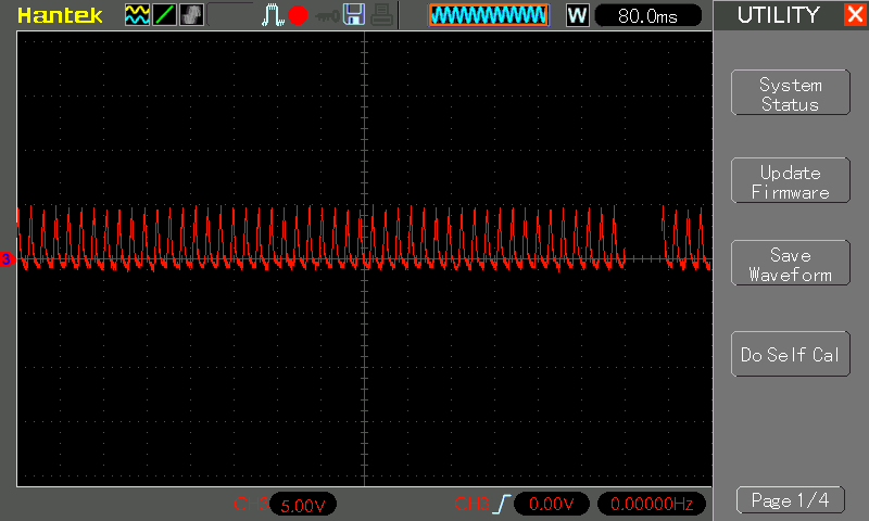
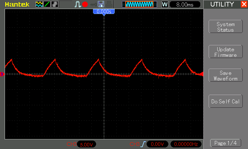
I'm doing a device - LED driver: 22V and 4A. The design of my device is almost completely identical to the reference design from the datasheet. When you start the device using the lamp it lights up and flashes showing short-circuit and overcurrent. At the gate of the transistor GT1 is present for PFC PWM the desired frequency (200 kHz), but the duty cycle always >90% and approaches 100%, creating a short circuit. At the gate of the transistor flyback Converter PWM is missing and there is always 0V.
Tell me what can be the error? I will be grateful for your help and advice!

My design: LED control.pdf

  • Hello Ilja,

    I have notified the appropriate team of your issue and you should receive a response from one of them soon.
    If they cannot find the error after examining the schematic diagram, I anticipate that they will request oscilloscope waveforms.
    Please prepare to acquire various waveforms in advance, to help speed up debug.

    Regards,
    Ulrich
  • Hi Ilja,

    I would like to see some waveforms. The bus voltage is set at about 430V. What does this look like at startup ?

    The pfc stage should start up with about 110Vdc on the bus. This corresponds to about 80Vac input.

    Please measure the voltage across C28 .

    You should  really begin testing your power supply with a variable resistive load. I don't know what your LED load looks like but a string of LEDs is a constant voltage load and you cannot simply connect it to fixed voltage (23V) output.

    Please look at the no load condition and slowly increase the load in,say, 50 Ohm steps.

    Regards,

    John Griffin

  • Thanks for the quick response, John!

    1) I changed R3 and R7 to the resistors 510 kOhm. This value for 390V

    2) I enable on the device when the line voltage is 230V.

    The signals are measured with no output load:

    1) Capacitor C28, the signal amplitude is about 320V -

    2) Gate VT2 -

  • When the load (50, 100 Ohm and lamp) is connected, the situation is not changed.
  • It's waveform on the pin number 9 (VCC) at startup -