This thread has been locked.

If you have a related question, please click the "Ask a related question" button in the top right corner. The newly created question will be automatically linked to this question.

TPS610985: High ripple / instability

Part Number: TPS610985

I have a design that includes the TPS610985 for supplying 3.0V system voltage from 2xAA Alkaline cells.

On some of my boards I encountered noise related issues. After some measurements I found that some boards had a large ripple (40-100 mVpp) on the power rail. The input voltage is around target voltage (2.8 ~ 3.0V).

System in active mode (medium draw 5-10mA):

System in sleep/idle mode (low draw < 50 uA):

When the load decreases (when the system goes in normal/sleep mode, draw is < 50uA) frequency decreases, when adding a 500Ohm test load across the power rail the frequency increases. The ripple amplitude stays fairly constant. Most of the boards I have don't seem to have this problem however. The good boards have a ripple < 10mV (if any) and only show a short transient when (dis)connecting loads.

Here's the layout of the DC converter:

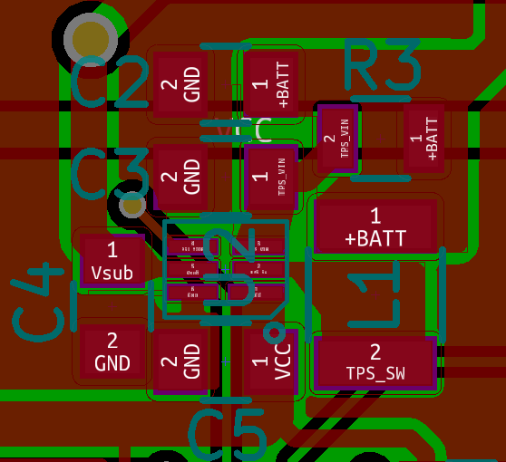
C2: 10uF MLCC input cap

C3: 100nF MLCC Vin decoupling

R3: 400Ohms

C4: 1uF MLCC VSub buffer

C5: 10uF MLCC VMain output cap (also tried 22uF)

L1: 4.7uH wire wound inductor (ferrite core, LQH3NPN4R7MMRE)

Maybe the (charge level, type) of the batteries plays a role? Could it be the inductance of the traces from the batteries to the converter cause the instability? Any comments on the layout? (in the next rev. I will put in a bunch of gnd-vias)

Ps. The device is running in the low-power mode (but switched when current > 10mA is drawn).

Thanks for looking into this!

  • could you also measure the SW pin voltage and zoom in to check how the device switches?
    it is not unstable. this device operates at PFM mode at light load condition. the ripple varies with the input voltage, load condition, and different device.

    by the way, how the ripple impact the system?
  • I think you're right in that the device operates normally (and is not in some unwanted/unstable oscillation). I have a target voltage of 3 Volt, but the actual output varies between 3.0 and 3.1 Volt between devices. Given that the input voltage of 2 fresh alkaline cells is also around 3.0~3.1 Volt causes different devices to operate in different modes (even when using the same test set of batteries). This explains the "non deterministic" behaviour of the DC-convertor.

    Still the actual ripple of 30-60 mVpp is quite large in my opinion, but maybe that's the trade-off for having a very low current device.

    The problems occur in the analog part of my system. I incorporate a PIR sensor, and the ripple causes false positive readings. Currently I'm experimenting with different filter topologies for powering the PIR sensor. (2nd order RC + zener input). I don't have any problems in the digital domain of the system. Possibly there's an application note available on powering sensitive analog circuitry of a switch mode DC-DC convertor ?
  • could you use the VMAIN of for the digital circuit and the Vsub for the analog circuitry? if the analog circuit is not always on. the Vsub from the LDO is low noise.