Other Parts Discussed in Thread: SN74LV125A
Hello,
I am working on a system that consists of a large series of TLC5916IPWR's daisy-chained together on multiple boards.
The system will involve 24 of these boards linked together, but the problem presents after just two boards are connected.
The issue I am seeing is that the digital data is corrupted between each board. The first board displays the correct pattern, but the next board lights the wrong pixels. Every board connected afterwards looks progressively worse. See two connected boards below with a simple alternating row pattern (first one on the right, second on the left. The first one has a dead pixel):
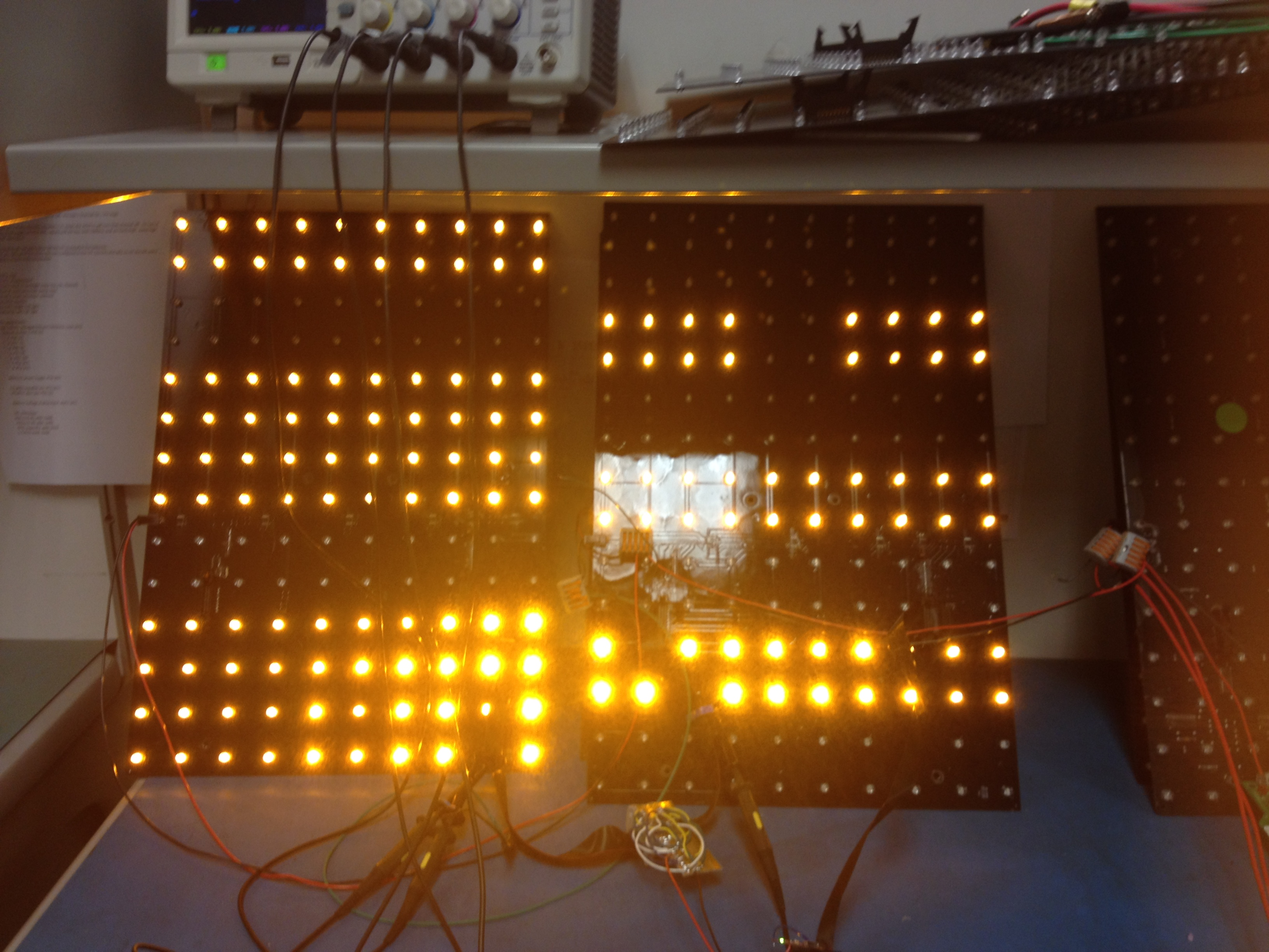
As you can see, the boards are very large (13"X19"), and are connected by a 6" ribbon cable. VSYS is provided by a 12V wall supply in testing, but it is designed to be supplied by a 12V battery. The brightness in the above image appears to vary because of narrow beam-width LEDs.
See board schematic below:

PDF version, for higher detail:
Missing from the schematics is that I have added 0.1uF (CHIP0402) decoupling to both buffers, an extra 10uF (CHIP1206) to the input of the linear regulator, and 47uF (Electrolytic radial lead, cut short) to the output of the linear regulator.
Given that the first board works fine, my assumption is the issue has to do with the interaction between the buffer and the LED drivers. Below are scope traces showing more information:
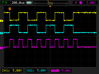
Digital Pulses:

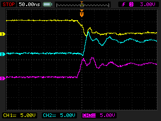
Zoomed in on an edge:
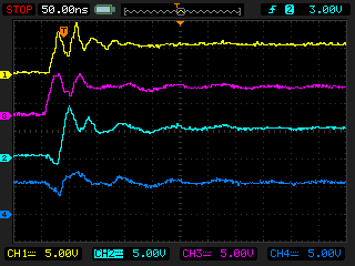
The yellow trace is CLK out of the buffer, the purple trace is CLK into the buffer, the teal trace is one of the SDI lines out of the buffer, and the blue trace is the 5V line measured at the VCC input of U2.
Those edges aren't pretty for sure, but they appear to be within spec (and are much better since I added the 1K resistor tied from CLK In to GND).
I was hoping you would have some idea why my serial data is getting corrupted, or some tips on how to debug further. Thank you for your time.
-Spencer Allen